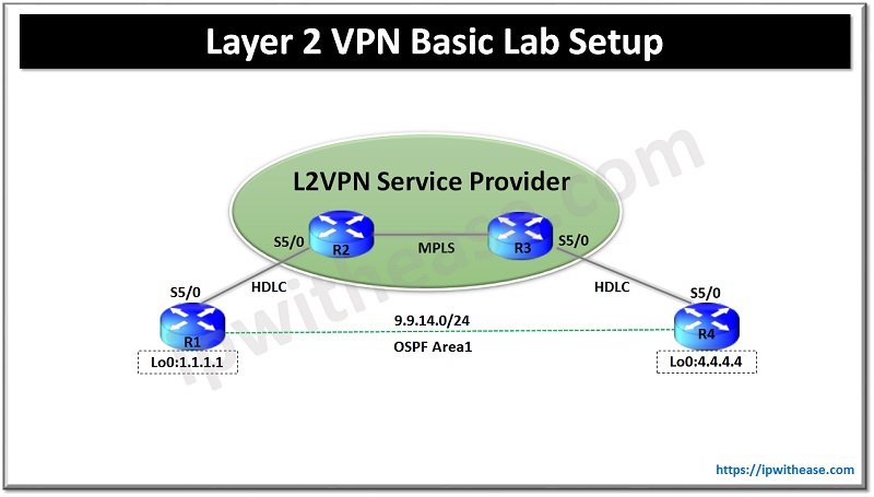
In this post we will configure a basic L2VPN setup using the topology diagram as shown below –
L2VPN Topology Explained
In the above topology R1 and R4 represent the CE routers at the two different sites of a single customer. R2 & R3 represent the provider backbone router which will be providing the L2 connectivity to the CE routers of the customer.
R1 & R2 are connected via serial link with the encapsulation type of default which is HDLC. R3 & R4 are connected via serial link with the encapsulation type of default which is HDLC.
We can have various types of encapsulation between CE and PE routers i.e. HDLC, PPP. Frame-relay, ATM and Metro-Ethernet but to keep it simple we have used the default of HDLC. The encapsulation is kept as HDLC on both the sides but we may have different encapsulation as well on both the sides.
For example R1 & R2 can be connected over HDLC encapsulation and R3 & R4 can be connected over any other encapsulation FR, ATM or PPP etc. In this case we require a little extra configuration which we will discuss in the upcoming posts.
Routers R1 and R2 doesn’t directly peer over L3 as provider will only provide L2 connectivity and wont peer over L3 and similarly between R3 and R4.We will form a VC between R1 & R4 and then they will peer using OSPF with each other and will be able to see the prefixes from each other.
Configurations: L2VPN
R1:
ip address 1.1.1.1 255.255.255.255
ip ospf 1 area 0
!
interface Serial5/0
ip address 9.9.14.1 255.255.255.0
ip ospf 1 area 0
serial restart-delay 0
R2:
ip address 9.9.0.2 255.255.255.255
ip ospf 1 area 0
!
interface FastEthernet0/0
ip address 9.9.23.2 255.255.255.0
ip ospf 1 area 0
mpls ip
!
interface Serial5/0
no ip address
serial restart-delay 0
xconnect 9.9.0.3 100 encapsulation mpls ##(In this command 9.9.0.3 is peer PE admin Loopack IP and 100 is the VCID)
R3:
ip address 9.9.0.3 255.255.255.255
ip ospf 1 area 0
!
interface FastEthernet0/0
ip address 9.9.23.3 255.255.255.0
ip ospf 1 area 0
mpls ip
!
interface Serial5/0
no ip address
serial restart-delay 0
xconnect 9.9.0.2 100 encapsulation mpls
Note: The VCID needs to be same on both the ends
R4:
ip address 4.4.4.4 255.255.255.255
ip ospf 1 area 0
!
interface Serial5/0
ip address 9.9.14.4 255.255.255.0
ip ospf 1 area 0
serial restart-delay 0
Verification
We see R2 and R3 now form a targeted LDP session by using the xconnect command:
R2# sh xconnect all
UP=Up DN=Down AD=Admin Down IA=Inactive
SB=Standby HS=Hot Standby RV=Recovering NH=No Hardware
XC ST Segment 1 S1 Segment 2 S2
——+———————————+–+———————————+–
UP pri ac Se5/0(HDLC) UP mpls 9.9.0.3:100 UP
Above command shows the VC 100 is up with encapsulation type as HDLC.
R2#sh mpls ldp neighbor
TCP connection: 9.9.23.3.40491 – 9.9.0.2.646 State: Oper; Msgs sent/rcvd: 14/14; Downstream Up time: 00:06:19 LDP discovery sources: FastEthernet0/0, Src IP addr: 9.9.23.3 Targeted Hello 9.9.0.2 -> 9.9.0.3, active Addresses bound to peer LDP Ident: 9.9.23.3 9.9.0.3 On R1 we see the OSPF neighbor ship is up with R4: R1#sh ip ospf neighbor 4.4.4.4 0 FULL/ – 00:00:33 9.9.14.4 Serial5/0
Further we see route from R4 on R1 for 4.4.4.4.
R1#sh ip route 4.4.4.4
Known via “ospf 1”, distance 110, metric 65, type intra area
Last update from 9.9.14.4 on Serial5/0, 00:07:40 ago
Routing Descriptor Blocks:
* 9.9.14.4, from 4.4.4.4, 00:07:40 ago, via Serial5/0
Route metric is 65, traffic share count is 1
Lastly we see we are able to ping from R1 to R4:
R1#ping 4.4.4.4 source 1.1.1.1
Sending 5, 100-byte ICMP Echos to 4.4.4.4, timeout is 2 seconds:
Packet sent with a source address of 1.1.1.1
!!!!!
Success rate is 100 percent (5/5), round-trip min/avg/max = 112/132/140 ms
Continue Reading:
Layer 2 vs Layer 3 VPN – Know the Difference
Types of Virtual Private Network (VPN) & its Protocol
ABOUT THE AUTHOR

I am here to share my knowledge and experience in the field of networking with the goal being – “The more you share, the more you learn.”
I am a biotechnologist by qualification and a Network Enthusiast by interest. I developed interest in networking being in the company of a passionate Network Professional, my husband.
I am a strong believer of the fact that “learning is a constant process of discovering yourself.”
– Rashmi Bhardwaj (Author/Editor)