Table of Contents
Introduction to OSPF Virtual Link
Virtual links are used to extend Area 0 across another area. They also can be thought of as tunnels for LSAs. They are deployed in cases when areas become partitioned or an area does not border Area 0. To configure a virtual link, use the following router command:
Router(config-route)#area “transit_area_id” virtual-link “router_id_of_remote”
The area_id is the “transit area” that OSPF will tunnel through. The “transit area” cannot be a stub area of any kind. At the end of the tunnel will be another router terminating the virtual link; use the router ID of that router in the router_id field. Virtual links use RIDs, and they are another reason why we use fixed RIDs when configuring OSPF. Remember that a virtual link is actually an extension of Area 0. Think of the virtual link as the router’s new interface into Area 0. Configure all interface options on the virtual link.
OSPF Virtual Link Configuration: Example Scenario
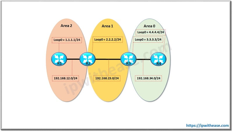
The Below example scenario will help illustrate where , when and how to use OSPF virtual link configuration in the OSPF domain –
As depicted in the diagram , we have 3 areas connected in series – Area 0 , Area 1 and Area 2.
The IP address , subnets and interface detail in respective area is shown in the table –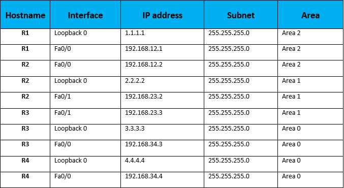
Once the OSPF is configured as per above table , we can see the OPSF neighborship formed amongst all the OSPF speaking routers R1 , R2, R3 and R4:
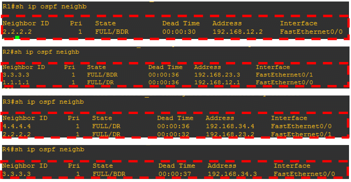
Now Lets see , how many routes R1 learns from its OSPF neighbor R2:

As we see, no Inter area (OIA) route is being learnt by R1 . The reason – OSPF rule book says , a non-backbone area cannot learn OSPF routes from another non backbone area , which means R1 (in Area 2) cannot learn OSPF routes of Area 1 (which again is another non-backbone area) directly.
Also , lets see whether R3 learns Area 2 routes:

And as expected , no routes learned by R3 for networks in Area 2
Now , how do we correct this situation and have OSPF to have R1 to learn routes from Area 1 and Area 0.
The solution is Virtual Link – We need to extend the Backbone (Area 0 ) via virtual link up to ABR Router R2.Note – Virtual link is a logical link using the least cost path between the ABR of the non-backbone connected area and the backbone ABR of the transit area.
The configuration needs to be performed in the transit area ABR routers ie between R2 and R3 as follows:

Now , lets see how the ospf neighbor tabe looks like after Virtual link is configured between ABRs R2 and R3:

Finally , its time to see whether R1 (Area 2) receives all the routes post configuration of virtual link between R2 and R3 (ABRs on transit Area 1).

The virtual link successfully extends Area 0 up to Area 2 (via transit area 1)

The Routers now have the complete routing table.
Another Scenario
Another Scenario where we need to implement virtual link –
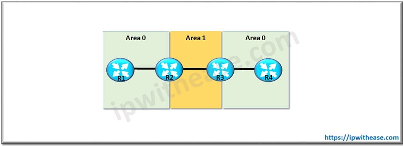
In the above topology, Area 0 has been split into 2 parts and separated by Area 1.
On the left side, R1 & R2 are in Area 0 and on the right side, R3 & R4 are again in Area 0, separated by Area 1 configured on directly connected interfaces of R2 & R3.
Since, Area 0 should be single backbone area unlike the above diagram. So, in order to render it a single backbone domain, a virtual link needs to be configured between R2 & R3. Once this configuration is done (i.e. single backbone area is configured) OSPF domain will not have any challenge and the database table would be consistent.
Continue Reading:
OSPF LSA Types: The Ultimate Guide
ABOUT THE AUTHOR

You can learn more about her on her linkedin profile – Rashmi Bhardwaj

