EIGRP K values
EIGRP uses a composite metric and K-values to calculate the preferred path to a destination.

EIGRP K Values Types –
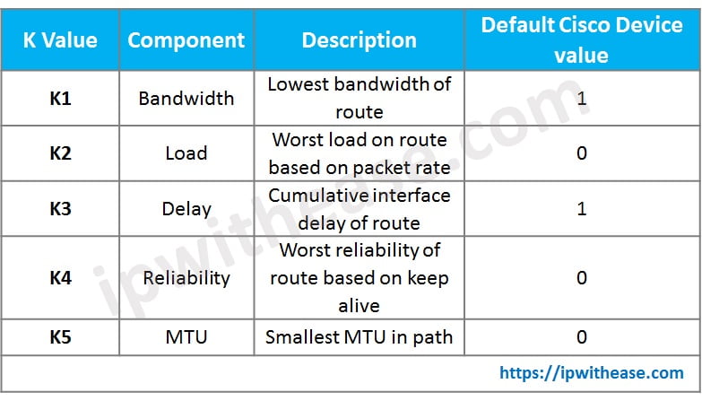
Below table details on the 5 K-value types and corresponding default Cisco value on devices while calculating EIGRP metric to a destination.
Related – EIGRP Interview Questions
EIGRP k values metric calculation –
The formula for the computation of EIGRP metric is –
It’s important to understand where to find the EIGRP k values in the Cisco network devices. The command “show interfaces (interface name)” will provide the detail of all the K-values i.e. Bandwidth, Load, delay, Reliability and MTU.

Another important show command to show the K values presently used the cisco device (default values) –
“Show ip protocols”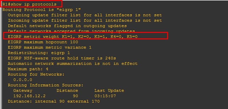
Now, let’s understand from an example scenario which will illustrate how EIGRP composite metric is calculated for Network 1.1.1.0/24 (Loopback 0 of Router R1). Routers R1, R2 and R3 are all connected in series with Loopback 0 of R1 (IP =1.1.1.1/24) advertised in EIGRP domain. We are considering default K-values calculation mechanism i.e. K1 = K3 = 1 and K2=K4=K5 = 0.
Related Bl0g – Configuring EIGRP Stub FEATURE
Computation formula –
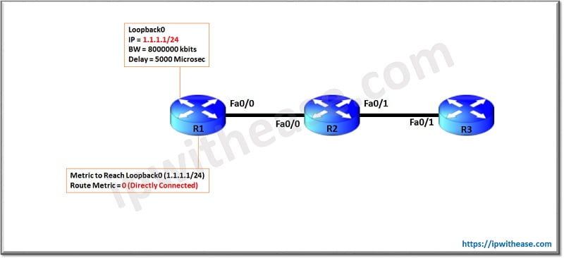
On Router R1, since Loopback 0 (1.1.1.0/24) is directly connected, hence the metric comes out to be 0. Now let’s see how R2 interprets metric for reaching Loopback 0 of R1 –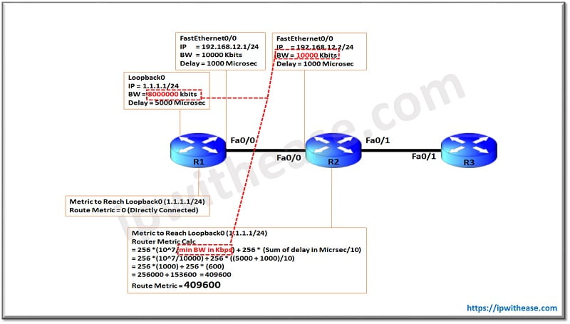
As above, the minimum bandwidth will be decided from one of the 2 i.e. (1) Loopback 0 of R1 (2) Interface fa0/0 of R2. For computation, bandwidth of 10000 Kbps of R2 interface Fa0/0 will be used since it’s the minimum of the 2.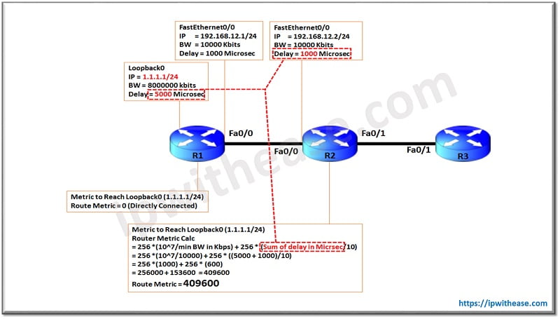
For Delay calculation, sum of both the (1) Loopback 0 of R1 and (2) Interface Fa0/0 of R2 will be taken. Hence total Delay (in microsec ) comes out to be 5000 + 1000 = 6000 Microseconds.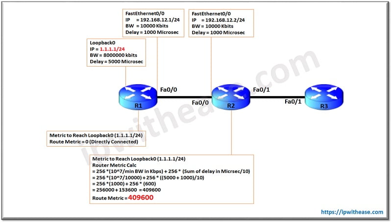
The final computation of metric for R2 to reach Loopback 0 of R1 comes to be 49600.Now let’s understand how R3 computes the Metric to reach Loopback 0 of R1.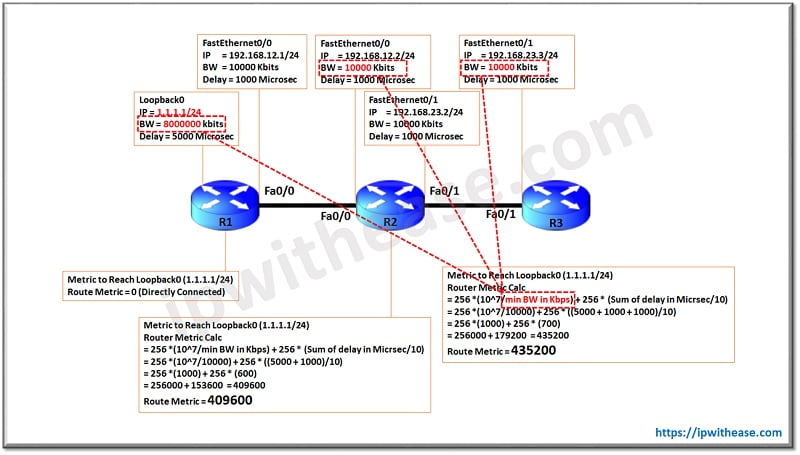
As above, the minimum bandwidth calculation will be taken from one the 3 interface bandwidths (1) Loopback 0 of R1 (2)Interface Fa0/0 of R2 (3) Interface Fa0/1 of R3
Since the minimal bandwidth is 10000 Kbps on Fa0/0 of R2 and Fa0/1 of R3, the same will be used in computation as shown in above diagram.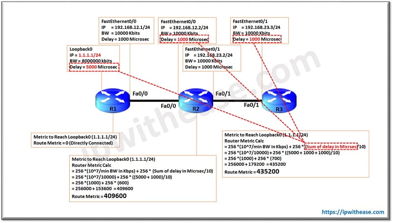
For Delay calculation, again sum of following interfaces will be considered – (1) Loopback 0 of R1 and (2) Interface Fa0/0 of R2 (3) Interface Fa0/1 of R3. Hence total Delay (in microsec) comes out to be 5000 + 1000 + 1000= 7000 Microseconds.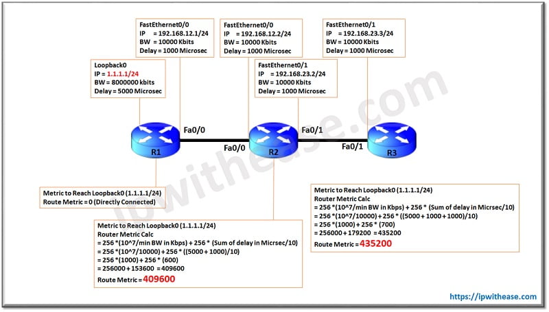
Now we have clear understanding of EIGRP composite metric is calculated by K values. In the above case the default values of K1 and K3 were used while calculating the composite metric for the destination.
Continue Reading:
EIGRP Preferred Path Manipulation
ABOUT THE AUTHOR

You can learn more about her on her linkedin profile – Rashmi Bhardwaj

Obrigado, me ajudou muito!