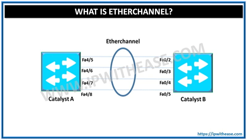
Ether-channel is a port link aggregation technology or port-channel architecture used primarily on switches. It allows grouping of several physical Ethernet links to create one logical Ethernet link for the purpose of providing fault-tolerance and high-speed links between switches, routers and servers.
Ether-channel Load balancing Algorithm
When there are multiple links available that will all carry traffic, the next question becomes, how will the traffic be load balanced across these links? The answer depends on many things, because Ether-Channel is selective enough to give out many options to load balance on. There are as –
- Source MAC address
- Destination MAC address
- Source and Destination MAC addresses
- Source IP address
- Destination IP address
- Source and Destination IP addresses
- Source Port number
- Destination Port number
- Source and Destination Port numbers
Scenarios of multiple (2, 4 or 8) link selection
– Selection of 2 Physical links
If we are given to use source and destination IP address as hashing criteria, with a port channel containing 2 physical links, we will XOR the last bit (remember binary bits can only be 0 or 1, and IP address is eventually just a 32 bit binary number) of the address to obtain either a 0 (then, it’s for link 1) or 1 (then, it’s for link 2).
– Selection of 4 Physical links
If for the same situation but with a port channel containing 4 physical links, we will XOR the last 2 bits of the address to obtain a 00 (for link 1), 01 (for link 2), 10 (for link 3), and 11 (for link 4). Now, you might wonder, what if we have an odd number of links, say 3. The answer is that we will still use the last 2 bits, but the traffic distributed to link 4 (which are non-existent) assigned to the 3 links in a round robin fashion.
If a single criteria is used (rather than source and destination IP address as specified above), such as the source MAC address, only the last 1, 2, or 3 bits will be used.
– Selection of 8 Physical links
If we have 8 links with subnets 10.1.0.0/16 to 10.8.0.0/16 and with ip addresses on both ends with first link 10.1.0.1—10.1.0.2 and so on to 10.8.0.1—10.8.0.2 on the last link. The links are bundled without any reference to IPs associated to other links, to which workstations are connected.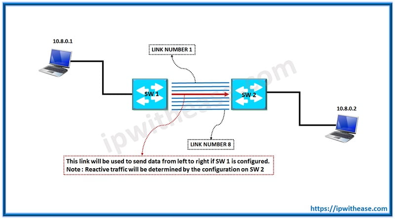
Now, if workstation with an IP 10.8.0.1 tries to send data to 10.8.0.2 at other end, this is what will happen: for src-dst IP
First IP – 10.8.0.1 Second IP – 10.8.0.2
Last three bits – 00000010 last three bits – 00000001
Note: The bits are last three bits from the whole IP address. You can also say that they are from the last octet as the last eight bits make the last octet. We use three bits if active links between switches are between 5 to 8, two bits if the active links are between three & four, one bit if the active links are between one & two.
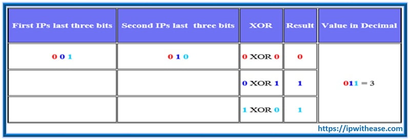
Therefore, when data will be sent from 10.8.0.1 to 10.8.0.2, the forth link between the switches will be used by the sending switch – 0 is First link, 1, 2, 3, 4, 5, 6 & 7 is Eighth link.
For src-ip it is much simpler. If the sending computer is 10.8.0.1, then the last three bits in the sending IP are 001. These convert to decimal value of 1 relating to link number 2 between the switches.
Dynamic Trunk Negotiation protocol:
Link aggregation can be dynamically achieved via 2 negotiation protocols namely –
- PAgP- CISCO proprietary
- LACP- IEEE 802.ad standard
Ether channel configuring command (Configuring PAgP/LACP)
Interface port-channel (channel group number)
Channel protocol PAgP/LACP
Channel-group mode (mode)
Configuring layer 2 ether-channel
Switch (config) # interface range interface slot/port
Specifies the interface to configure in bundle
Switch (config-if-range) # channel-protocol (PAgP | LACP)
Specifies the channel protocol either PAgP or LACP
Switch (config-if-range) # channel-group number mode (active | on | auto | desirable | Passive)
Creates the port-channel interface and places the interface as member
Configuring layer 3 ether-channel
Switch (config) # interface port-channel port-channel number
Creates a port channel interface
Switch (config) # no switchport
Switch (config) # ip address mask
Specifies an layer 3 and assign IP address and subnet mask to ether-channel
Switch (config) # interface slot/slot
Specify an interface to configure
Switch (config) # no switchport
Switch (config) # channel-group number mode (auto | desirable | on)
Configure the interface as Layer 3 and specifies the port-channel as PAgP mode
Conditions for an Ether-channel formation
Verify ether-channel status and configurations
Switch # Show running-config interface port-channel number
Display port-channel information
Switch# Show running-config interface interface slot/port
Display interface information
Switch# sh interface g0/1 ether-channel
Switch# Show ether-channel 1 port-channel
Switch# Show ether-channel 1 summary
Guidelines for configuring ether-channel
- All ether-channel must support ether-channel with no contingencies.
- All interfaces in an ether-channel must be configured at same speed and duplex.
- Ether-channel will not form if one of the interface is a switched port analyzer destination port.
- IP Address must be assign to a port-channel logical interface in layer 3 ether-channel.
- Interface must be assign to same VLAN or configured as trunk in layer 2 ether-channel.
- All interface must support the same allowed range of VLAN’s
- Interface in same bundle san support varying port cost.
- Port-channel interface configuration changes affect the ether-channel.
- Physical interface configuration changes affect the interface only.
Benefits of using EtherChannel
- Increased Bandwidth: Use EtherChannel and combine two or four links into one logical link. For example, four 100Mb Fast Ethernet connections bonded into one could provide you up to 800Mb/second, full duplex.
- Link Redundancy: It automatically allows more available links in case one or more links go down.
- Load Balance Traffic: EtherChannel balances the traffic load across the links, thereby increasing efficiency on your networks.
Summary
- Ether-channel increase bandwidth and provide redundancy by aggregating individual links between switches.
- Ether-channel can be dynamically configured between switch using either PAgP & LACP.
- Ether-channel is configured and verified using a variety of show command.
- Ether-channel load balance traffic over all links in bundle.
ABOUT THE AUTHOR

You can learn more about her on her linkedin profile – Rashmi Bhardwaj

