Table of Contents
Multi-Chassis Link Aggregation or MLAG is a network technology that allows two or more network switches to appear as a single logical switch for link aggregation, which provides redundancy and load balancing.
In this blog, we discuss the Multi-Chassis LAG technology in detail, it’s terminology, features, benefits and configuration steps. Before understanding MLAG, its important to understand the concept of LAG.
What is LAG?
LAG a.k.a Link Aggregation is a technology where multiple links from a switch chassis were bundled together and connected to multiple links on the neighbor switch chassis to provide increased bandwidth capacity. Multiple links combined act as one logical link and in case any physical link fails the traffic is automatically shifted onto another link in bundle hence providing some redundancy. However in LAG in case a switch chassis goes faulty then there is no redundancy.

What is MLAG?
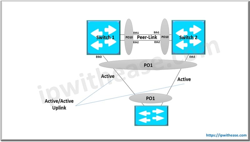
MLAG or Multi-chassis Link aggregation is an enhancement of LAG where the ports from different switch chassis are bundled together to act as a single logical link. This also provides active/active uplinks with no layer 2 loops. MLAG switch is much similar to VPC feature in Cisco Nexus but MLAG being non-proprietary.

MLAG Terminology
- MLAG Domain – A pair of physical switches
- MLAG peer – A single switch within an MLAG domain
- MLAG peer-link – Ethernet physical link between MLAG peers required to synchronize state between MLAG peers and carry user data
- MLAG member port – One or more user-facing physical ports that forms an MLAG
- MLAG port-channel – This is a combined user-facing port-channel between MLAG peers consisting of MLAG member ports on both MLAG peers
- MLAG VLAN – A VLAN used exclusively on the MLAG peer-link, in order to aid control-plane communication between MLAG peers.
Features of MLAG
- Multi-Chassis Support: It combines two switches to act as a single logical unit.
- Active-Active Link Aggregation: Both switches actively forward traffic, improving link utilization.
- Independent Control Planes: Each switch maintains its own control plane while synchronizing key data.
- Peer Link and Keepalive Link: Uses peer communication channels to synchronize MAC tables and detect failures.
- Non-Blocking Topologies: Supports high-performance, loop-free network topologies without Spanning Tree Protocol (STP).
- Interoperability with Standard LAG (IEEE 802.3ad): Works with standard LACP-based link aggregation on connected devices.
- Failover Mechanism: Provides redundancy by continuing operations if one switch fails.
Benefits of MLAG
- High Availability & Redundancy: Traffic continues to flow even if one switch or link fails, reducing downtime.
- Improved Bandwidth Utilization: Enables full use of aggregated links by leveraging both switches.
- No Spanning Tree Bottlenecks: Eliminates STP blocking, allowing all links to be active simultaneously.
- Simplified Network Design: Reduces complexity by replacing traditional STP-based designs with more efficient, resilient setups.
- Increased Scalability: Supports seamless expansion by adding more uplinks or switches.
- Load Balancing: Spreads traffic across multiple links and switches for better performance.
- Fast Convergence: Rapid failover and recovery compared to traditional STP mechanisms.
- Vendor Flexibility (in some implementations): Some MLAG implementations can work across different vendors with standard protocols like LACP.
Multi-Chassis LAG Configuration Steps
Step 1: Configure the Peer Link
There should be a minimum of two ports for redundancy and under normal circumstances peer link shouldn’t be used to carry any data-traffic.
Switch1(config)#interface eth 1-2
Switch1(config-if-Et1-2)#channel-group 10 mode active

Switch1(config-if-Et1-2)#interface port-channel 10

Switch1(config-if-Po10)#switchport mode trunk
Switch2(config)#interface eth 1-2
Switch2(config-if-Et1-2)#channel-group 10 mode active
Switch2(config-if-Et1-2)#interface port-channel 10
Switch2(config-if-Po10)#switchport mode trunkStep 2: Create the Peer Link VLAN
It is the VLAN used for MLAG TCP/UDP session. SVI should be configured on both peers and Spanning-tree needs to be disabled.
Switch1(config)#vlan 4094
Switch1(config-vlan-4094)#trunk group mlag

Switch1(config)#int vlan 4094

Switch1(config-if-Vl4094)#ip address 10.10.10.1/30

Switch1(config-if-Vl4094)#no autostate  #Required to bring the VLAN 4094 SVI up as it isnt a member of any physical port.

Switch1(config)#int port-channel 10

Switch1(config-if-Po10)#switchport trunk group mlag

Switch1(config)#no spanning-tree vlan 4094
Switch2(config)#vlan 4094
Switch2(config-vlan-4094)#trunk group mlag
Switch2(config)#int vlan 4094
Switch2(config-if-Vl4094)#ip address 10.10.10.2/30
Switch2(config-if-Vl4094)#no autostate #Required to bring the VLAN 4094 SVI up as it isnt a member of any physical port.
Switch2(config)#int port-channel 10
Switch2(config-if-Po10)#switchport trunk group mlag
Switch2(config)#no spanning-tree vlan 4094Step 3: Configure the MLAG Domain
Switch1(config)#mlag
Switch1(config-mlag)#domain-id Admin

Switch1(config-mlag)#peer-link port-Channel 10

Switch1(config-mlag)#local-interface vlan 4094

Switch1(config-mlag)#peer-address 10.10.10.2
Switch2(config)#mlag
Switch2(config-mlag)#domain-id Admin
Switch2(config-mlag)#peer-link port-Channel 10
Switch2(config-mlag)#local-interface vlan 4094
Switch2(config-mlag)#peer-address 10.10.10.1Step 4: Create the MLAG Port Members
Switch1(config)#interface eth 3
Switch1(config-if-Et3)#channel-group 1 mode active

Switch1(config-if-Et3)#int port-Channel 1

Switch1(config-if-Po1)#switchport mode trunk

Switch1(config-if-Po1)#mlag 1


Switch1(config-if-Po1)#show port-channel 1

Port Channel Port-Channel1:

Active Ports: Ethernet3 PeerEthernet3
Switch2(config)#interface eth 3
Switch2(config-if-Et3)#channel-group 1 mode active
Switch2(config-if-Et3)#int port-Channel 1
Switch2(config-if-Po1)#switchport mode trunk
Switch2(config-if-Po1)#mlag 1
Switch2(config-if-Po1)#show port-channel 1
Port Channel Port-Channel1:
Active Ports: Ethernet3 PeerEthernet3To verify the MLAG peer you can run the command “show mlag detail”
Related- Multi Chassis Trunking (MCT) Terminologies
ABOUT THE AUTHOR

You can learn more about her on her linkedin profile – Rashmi Bhardwaj


