Clos architecture/Clos Network was invented in 1938 by Edson Erwin and in 1952 Charles Clos made the telephone node inter communication using this solution. Charles Clos published a paper titled “A Study of Non-blocking Switching Networks” in the Bell System Technical Journal in 1953.
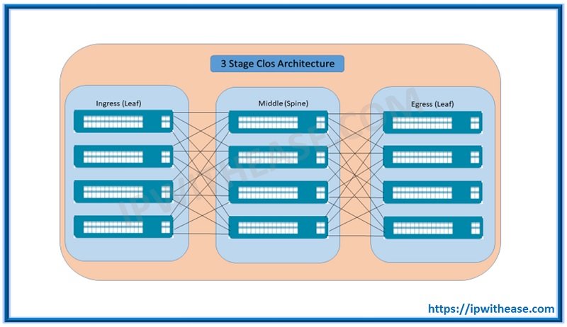
The Clos network is one of the way to design a multistage Network and the 3-stage Clos is the smallest version of a Clos Network. It has 3 stages:
- Ingress Stage
- A Middle Stage and
- An Egress stage.

STAGES OF CLOS ARCHITECTURE/CLOS NETWORK
A Clos Network is built on odd numbers, starting with 3, a 5, 7 and so on stages in Clos is possible.
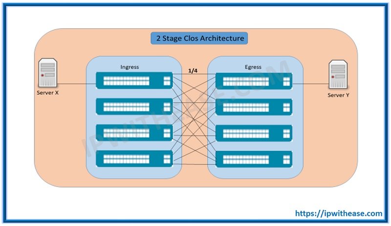
So now the question is why we cannot start ip Clos network with 2 stages. The very simple answer is that two stage Clos cannot provide us Non-Blocking connectivity because it doesn’t provide us multiple path from one switch to another or even if you have multiple path but it cannot provide you ECMP.
So Let’s Understand from the Diagram:
As shown in the above diagram, if Server X want to communicate Server Y it will have only one path (so that mean only ¼ of ports are connected, rest are not connected so it blocking you)
Related – Cisco Spine and Leaf Network Topology
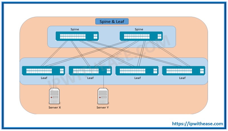
A spine and Leaf network is similar to 3-stage Clos network. It is sometimes also referred to as folded 3-stage Clos Network, in which the Ingress and Egress Points Are folded back on top of each other.
The Spine Leaf Topology is based on Clos Architecture, which has two layers: –
- Spine: it’s a backbone of the network and it connects all leaf switches.
- Leaf: It consist of access switches that connect to devices like: – Server, Router, Firewall, IDP/IPS etc.

Understanding of Spine Leaf Terms
- No Device Connects to spine, because it is only designed to pass traffic between leafs.
- All links between spine and leaf are Layer 3 (Routed protocol use like EIGRP, OSPF, ISIS etc.)
- In this topology every leaf is one hop away from other leaf, therefore it provides high bandwidth, low-latency, non-blocking server to server connectivity.
- If link on spine switch fails, ECMP is used to recover it.
- There are no links between Spines and leaves, thus making topology consistent and avoid unnecessary path.
- Its scalable solution. If we need more hosts, add more switches at leaf.
- It’s a routed network, which limits to Layer 2 domain and adding VXLAN on the top it allows to move traffic without changing IP address. It also focuses on the east and west traffic pattern.
Related – VXLAN Header
Before the industry settled on IP routing within the datacenter, various solutions were proposed to support bridging as the interconnect without STP. Solutions such as Trill and Shortest Path Bridging (SPB), and cisco FabricPath were deployed in some networks which used Mac-in-Mac frame Encapsulation.
Most common overlay protocol today uses either: –
- Mac-in-Mac encapsulation such as an IETF transport inter connection of lots of links (TRILL), and cisco fabric path.
- Mac -in-IP encapsulation can be achieved using NVGRE or VXLAN.
Note: – Overlay is a virtual network that is built on top of an undelaying network infrastructure (Related technologies are VXLAN, NVGRE, TRILL). Overlay network uses underlay network as transport infrastructure.
ABOUT THE AUTHOR

You can learn more about her on her linkedin profile – Rashmi Bhardwaj

