The multicast we usually hear is of 2 types, “Any Source Multicast” and “Source Specific Multicast”. Any source multicast has 2 flavors namely PIM Sparse mode and PIM Dense mode about which we have already discussed in out multicast basics post. Both the flavors of ASM use the IGMPV2. In ASM the receivers don’t know about the source initially and require a rendezvous point in the network to get to know about the active source.
Source Specific Multicast (SSM) uses IGMPV3 and in this the receivers don’t need a Rendezvous point as they know about the source specifically. In SSM there are no shared trees and only shortest path trees are built towards the source.
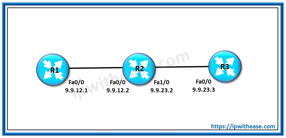
Let us take a simple topology below to configure the SSM:

R1 acts as the source and R3 acts as the receiver –
Step 1: Enabling the Multicast routing on all routers along with an IGP (OSPF)
router ospf 1
network 0.0.0.0 255.255.255.255 area 0
R1(config-if)#ip pim sparse-modeR2(config)#interface fastEthernet 0/0
R2(config-if)#ip pim sparse-mode
R2(config-if)#interface fastEthernet 1/0
R2(config-if)#ip pim sparse-mode
R3(config)#interface fastEthernet 0/0
R3(config-if)#ip pim sparse-mode
Step 3: Enable SSM on all routers
R2(config)#ip pim ssm default
R3(config)#ip pim ssm default
Step 4: Enable IGMPV3 on source and receiver
R1(config-if)#ip igmp version 3
R3(config)#interface fastEthernet 0/0
R3(config-if)#ip igmp version 3
R3(config-if)#ip igmp join-group 232.1.1.1 source 9.9.12.1
Now let us check the multicast routing table at R2
R2#sh ip mroute
Flags: D – Dense, S – Sparse, B – Bidir Group, s – SSM Group, C – Connected,
L – Local, P – Pruned, R – RP-bit set, F – Register flag,
T – SPT-bit set, J – Join SPT, M – MSDP created entry, E – Extranet,
X – Proxy Join Timer Running, A – Candidate for MSDP Advertisement,
U – URD, I – Received Source Specific Host Report,
Z – Multicast Tunnel, z – MDT-data group sender,
Y – Joined MDT-data group, y – Sending to MDT-data group,
G – Received BGP C-Mroute, g – Sent BGP C-Mroute,
Q – Received BGP S-A Route, q – Sent BGP S-A Route,
V – RD & Vector, v – Vector
Outgoing interface flags: H – Hardware switched, A – Assert winner
Timers: Uptime/Expires
Interface state: Interface, Next-Hop or VCD, State/Mode
(9.9.12.1, 232.1.1.1), 00:00:06/00:03:24, flags: sT
Incoming interface: FastEthernet0/0, RPF nbr 9.9.12.1
Outgoing interface list:
FastEthernet1/0, Forward/Sparse, 00:00:06/00:03:24
(*, 224.0.1.40), 00:02:47/00:02:58, RP 0.0.0.0, flags: DCL
Incoming interface: Null, RPF nbr 0.0.0.0
Outgoing interface list:
FastEthernet1/0, Forward/Sparse, 00:02:30/00:00:29
FastEthernet0/0, Forward/Sparse, 00:02:44/00:02:58
In the output above you see how R2 has built a SPT from source to receiver.
R3#sh ip igmp groups 232.1.1.1 detail
SS – Static Source, VS – Virtual Source,
Ac – Group accounted towards access control limit
Interface: FastEthernet0/0
Group: 232.1.1.1
Flags: L SSM
Uptime: 00:03:29
Group mode: INCLUDE
Last reporter: 9.9.23.3
Group source list: (C – Cisco Src Report, U – URD, R – Remote, S – Static,
V – Virtual, M – SSM Mapping, L – Local,
Ac – Channel accounted towards access control limit)
Source Address Uptime v3 Exp CSR Exp Fwd Flags
9.9.12.1 00:01:48 00:02:39 stopped Yes RL
192.168.12.1 00:03:29 00:02:39 stopped Yes RL
Related- Multicast Address
ABOUT THE AUTHOR

You can learn more about her on her linkedin profile – Rashmi Bhardwaj


