Table of Contents:
In this article, we will discuss the configuration of Integrated Routing and Bridging over WAN.
What is IRB?
IRB stands for Integrated Routing and Bridging. IRB technology helps a router to bypass its default behavior (router by default does not allow broadcast to be passed from one interface to another). With the help of IRB, Layer 2 broadcast can be forwarded from one interface to another in a router and at the same time routing of traffic can also be rendered.
In simple words, we can say that IRB is a technology that allows a protocol to be bridged as well as routed on the same interface on a router.
Unlike new technologies like VPLS, L2TP, OTV etc., IRB is quite older and was widely used on the WAN edge when the new technologies were not introduced.
Configuring Integrated Routing and Bridging (IRB) over WAN
Requirement:
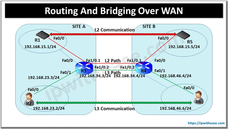
I have 2 sites namely Site A and Site B both having own User and Server Zones. Both the sites are connected over Point-to-Point link and communication across User VLANs works fine via routing over WAN (Static Routes).But applications in Server VLAN across sites are required to be on same IP Subnet (a common Layer 2 Broadcast domain). To summarize, the proposed solution should provide –
1. Routing across WAN links for USER-USER Layer 3 communication.
2. Bridging across WAN Links for SERVER-SERVER Layer 2 Communications.
Related – PTP LINKS (POINT TO POINT LINKS)
Scenario 1
In Scenario-1, The WAN (PTP) link terminates on Router at both the sites.
Scenario 2
In Scenario-2, The WAN (PTP) link terminates on L3 Switches at both the sites.
Proposed Solution
IRB (Integrated Routing and Bridging) will be incorporated in this scenario to provide both the Routing and switching functionality.
Note: -To keep things simple, routers will play the role of all endpoints i.e. as servers (R1,R5) or laptop/pc users (R2,R6).
Solution: Scenario 1
(PTP WAN Link termination on WAN Routers)
R1 –
Interface FastEthernet0/0
ip address 192.168.15.1 255.255.255.0
R2 –
ip route 0.0.0.0 0.0.0.0 192.168.23.3
!
interface FastEthernet0/0
ip address 192.168.23.2 255.255.255.0
R3 –
bridge irb
# Configure IRB (Integrated Routing and Bridging) to get both the routing and Bridging on R3 Router)#
bridge 1 protocol ieee
# Configure bridge protocol#
!
interface FastEthernet0/0
no ip address
bridge-group 1
!
interface FastEthernet0/1
ip address 192.168.23.3 255.255.255.0
!
interface FastEthernet1/0
no ip address
!
interface FastEthernet1/0.1
encapsulation dot1Q 1 native
bridge-group 1
!
interface FastEthernet1/0.2
encapsulation dot1Q 2
ip address 192.168.34.3 255.255.255.0
!
ip route 0.0.0.0 0.0.0.0 192.168.34.4
R4 –
bridge irb
bridge 1 protocol ieee
!
interface FastEthernet0/0
no ip address
bridge-group 1
!
interface FastEthernet0/1
ip address 192.168.46.4 255.255.255.0
!
interface FastEthernet1/0
no ip address
!
interface FastEthernet1/0.1
encapsulation dot1Q 1 native
bridge-group 1
!
interface FastEthernet1/0.2
encapsulation dot1Q 2
ip address 192.168.34.4 255.255.255.0
!
ip route 0.0.0.0 0.0.0.0 192.168.34.3
R5 –
interface FastEthernet0/0
ip address 192.168.15.5 255.255.255.0
R6 –
interface FastEthernet0/0
ip address 192.168.46.6 255.255.255.0
!
ip route 0.0.0.0 0.0.0.0 192.168.46.4
Acceptance Criteria –
R1#ping 192.168.15.5
Type escape sequence to abort.
Sending 5, 100-byte ICMP Echos to 192.168.15.5, timeout is 2 seconds:
!!!!!
Success rate is 100 percent (5/5), round-trip min/avg/max = 24/59/88 ms
R2#ping 192.168.46.6
Type escape sequence to abort.
Sending 5, 100-byte ICMP Echos to 192.168.46.6, timeout is 2 seconds:
!!!!!
Success rate is 100 percent (5/5), round-trip min/avg/max = 28/60/100 ms
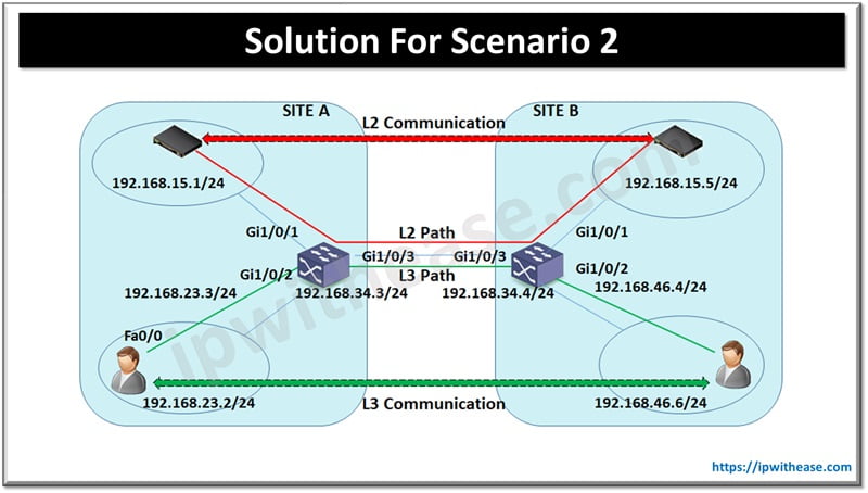
Solution: Scenario 2
(PTP WAN Link termination on L3 Switches Switches)
R1 –
Interface FastEthernet0/0
ip address 192.168.15.1 255.255.255.0
R2 –
ip route 0.0.0.0 0.0.0.0 192.168.23.3
!
Interface FastEthernet0/0
ip address 192.168.23.2 255.255.255.0
SW3 –
Interface gigabitethernet1/0/1
switchport
switchport mode access
switchport access vlan 1
!
interface gigabitethernet1/0/2
switchport
switchport mode access
switchport access vlan 2
!
interface FastEthernet1/0/3
switchport
switchport trunk encapsulation dot1q
switchport trunk allowed vlan 1,3
switchport mode trunk
# Configure trunk link on WAN PTP link and allow both the Vlans 1 and 3 #.
!
interface Vlan 2
ip address 192.168.23.3 255.255.255.0
!
interface Vlan 3
ip address 192.168.34.3 255.255.255.0
!
ip route 0.0.0.0 0.0.0.0 192.168.34.4
SW4 –
Interface gigabitethernet1/0/1
switchport
switchport mode access
switchport access vlan 1
!
Interface gigabitethernet1/0/2
switchport
switchport mode access
switchport access vlan 2
!
Interface FastEthernet1/0/3
switchport
switchport trunk encapsulation dot1q
switchport trunk allowed vlan 1,2
switchport mode trunk
!
interface Vlan 2
ip address 192.168.46.4 255.255.255.0
!
interface Vlan 3
ip address 192.168.34.4 255.255.255.0
!
ip route 0.0.0.0 0.0.0.0 192.168.34.3
R5 –
interface FastEthernet0/0
ip address 192.168.15.5 255.255.255.0
R6 –
interface FastEthernet0/0
ip address 192.168.46.6 255.255.255.0
!
ip route 0.0.0.0 0.0.0.0 192.168.46.4
Acceptance Criteria –
R1#ping 192.168.15.5
Type escape sequence to abort.
Sending 5, 100-byte ICMP Echos to 192.168.15.5, timeout is 2 seconds:
!!!!!
Success rate is 100 percent (5/5), round-trip min/avg/max = 24/59/88 ms
R2#ping 192.168.46.6
Type escape sequence to abort.
Sending 5, 100-byte ICMP Echos to 192.168.46.6, timeout is 2 seconds:
!!!!!
Success rate is 100 percent (5/5), round-trip min/avg/max = 28/60/100 ms
ABOUT THE AUTHOR

You can learn more about her on her linkedin profile – Rashmi Bhardwaj

