This article shares some of design practices I worked on while keeping high availability and network availability considerations in mind.
One such scenario came across when there was single Internet Link terminating on Cisco 2951 Router. The Router was required to downlink to Layer 2 Switch Stack and switch stack further terminated on pair of Firewall.
Related – Network Desing Interview Questions & Answers
Firewall Cluster has a requirement that both the chassis of Firewall outside interfaces should be part of same VLAN. Now comes the challenge – The default behaviour of all the 3 onboard ports of Cisco 2951 Router is to work as layer 3.
Below diagram for our understanding –
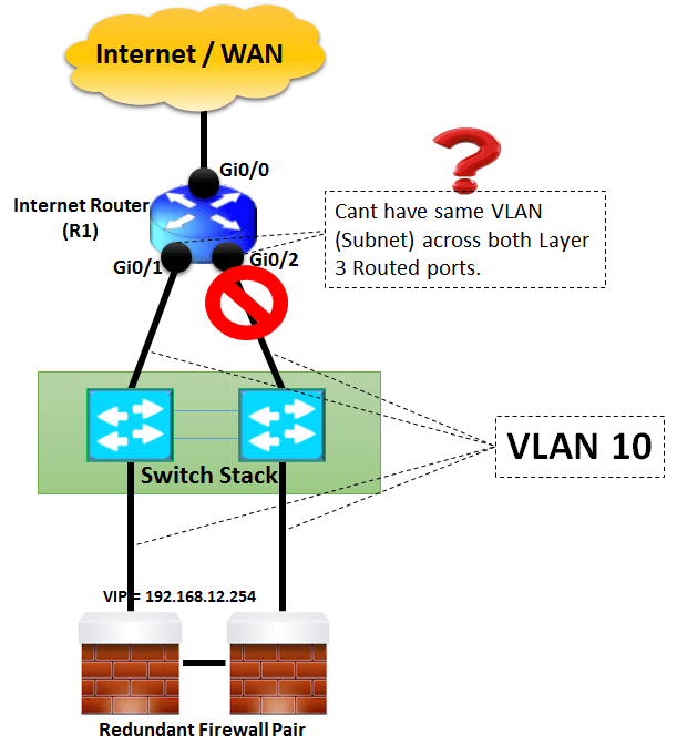
Lets see the CLI output on R1 to confirm above discussed understanding –
R1(config-if)#no shut
R1(config-if)#ip address 192.168.12.1 255.255.255.0
R1(config)#int Gi0/2
R1(config-if)#no shut
R1(config-if)#ip address 192.168.12.2 255.255.255.0
% 192.168.12.0 overlaps with GigabitEthernet0/1
Now, going back to drawing board, some options can be explored on ways to resolve this problem. One solution surely in mind is by using BVI (Bridged virtual Interface) where both the ports Gi0/1 and Gi0/2 would be made part of same Bridge Group.
Another approach may be to add EHWIC-4ESG card (4-port Cisco Gigabit EtherSwitch 10/100/1000BASE-TX autosensing EHWIC). The price also is not too highCisco EtherSwitch EHWICs do not support routed ports hence an SVI will be created to provide Layer 3 functionality.
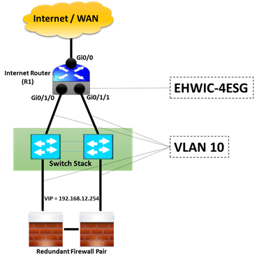
Step 1 –
Vlan 10 will be created
R1(config)#exit
Step 2 –
R1(config)#Switchport mode access
R1(config)#Switchport access vlan 10
R1(config)#no shut
Verify with following command –
VLAN Name Status Ports
—- ——————————– ——— ——————————-
1 default active Gi0/1/2, Gi0/1/3
10 VLAN0010 active Gi0/1/0, Gi0/1/1
1002 fddi-default active
1003 token-ring-default active
1004 fddinet-default active
1005 trnet-default active
Step 3 –
Provide IP address to SVI on R1
R1(config-if)#ip address 192.168.12.1 255.255.255.0
Step 4 –
Now it’s time to verify whether R1 can reach the logical IP 192.168.12.254 of Firewall Cluster.
During normal working –
VLAN10
Spanning tree enabled protocol ieee
Root ID Priority 32768
Address c200.3230.0001
This bridge is the root
Hello Time 2 sec Max Age 20 sec Forward Delay 15 secBridge ID Priority 32768
Address c200.3230.0001
Hello Time 2 sec Max Age 20 sec Forward Delay 15 sec
Aging Time 300Interface Designated
Name Port ID Prio Cost Sts Cost Bridge ID Port ID
GigabitEthernet0/1/0 128.41 128 4 FWD 0 32768 c200.3230.0001 128.41
GigabitEthernet0/1/0 128.42 128 4 BLK 0 32768 c200.3230.0001 128.41
As seen from the “sh spanning- vlan 10 brief” output , Interface Gi0/1/0 is in STP forwarding mode while Gi0/1/0 is being blocked by STP.
Next,ping test is carried from Firewall cluster (for testing a Router is been configured as Firewall).
Type escape sequence to abort.
Sending 5, 100-byte ICMP Echos to 192.168.12.1, timeout is 2 seconds:
!!!!!
Success rate is 100 percent (5/5), round-trip min/avg/max = 28/44/68 ms
Firewall#
The above output shows that firewall is able to ping R1 IP 192.168.12.1 via R1 interface Gi1/0/0 which is in forwarding state.
Next , shut interface Gi0/1/0
R1(Config-if)#shut
Once , Gi0/1/0 is shut , STP comes to play and moves Gi0/1/1 to Forwarding from earlier Blocking state as below –
VLAN10
Spanning tree enabled protocol ieee
Root ID Priority 32768
Address c200.3230.0001
This bridge is the root
Hello Time 2 sec Max Age 20 sec Forward Delay 15 secBridge ID Priority 32768
Address c200.3230.0001
Hello Time 2 sec Max Age 20 sec Forward Delay 15 sec
Aging Time 300
Interface Designated
Name Port ID Prio Cost Sts Cost Bridge ID Port ID
GigabitEthernet0/1/1 128.42 128 4 FWD 0 32768 c200.3230.0001 128.42
Now , let’s view the ping output from Firewall (IP 192.168.12.254) towards IP 192.168.12.1 with R1 interface Gi0/1/0 shut and Gi0/1/1 forwarding the traffic.
Type escape sequence to abort.
Sending 5, 100-byte ICMP Echos to 192.168.12.1, timeout is 2 seconds:
!!!!!
Success rate is 100 percent (5/5), round-trip min/avg/max = 28/44/68 ms
The output shows that using Cisco Switch EHWIC-4ESG on 2951 Router, we can achieve high availability on links using SVI based Routing between Router, Stack Switch and Firewall cluster.
ABOUT THE AUTHOR

You can learn more about her on her linkedin profile – Rashmi Bhardwaj

