Q IN Q TUNNELING
SCENARIO PURPOSE –
To extend customer VLAN 50 across customer WAN environment from Site A (CPE1) to Site B (CPE2).
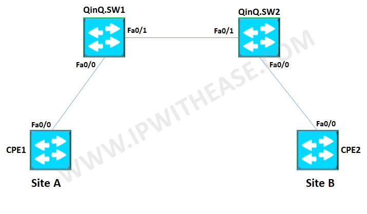
Below us the diagram for reference where customer has 2 locations Site A (CPE1) and Site B (CPE2) which need to communicate over service provider network (includes QinQ.SW1 and QinQ.SW2)
STEP 1 –
Let’s configure the customer switch (CPE1) to put the interface facing the service provider on VLAN 50. Note – It is considered that before this configuration , both the service provider switches QinQ.SW1 and QinQ.SW2 have been configured to support MTU more than 1500 by issuing “system mtu 1504” command and system has been rebooted to bring this change into effect. Configure the service provider switch interface facing customer CPE1 device in Q-in-Q mode. Also, we will assign tag of 200. Configure the interfaces between the Service Providers (QinQ.SW1 and QinQ.SW2) with basic trunk. The interface on QinQ.SW2 facing the customer side is assigned the same metro-tag of 200. Configure the customer equipment (CPE2) to include interface facing the service provider (QinQ.SW2) in VLAN 50. You can learn more about her on her linkedin profile – Rashmi Bhardwaj
interface FastEthernet0/0
Description CPE1 to QinQ.SW1
Switchport
switchport mode access
switchport access vlan 50
end
interface vlan50
ip address 50.50.50.1 255.255.255.0
endSTEP 2 –
interface FastEthernet0/0
Description CPE1 to QinQ.SW1
Switchport
switchport mode access
switchport access vlan 200 ——– This is referred to as customer tag vlan.
switchport mode dot1q-tunnel
l2protocol-tunnel cdp
l2protocol-tunnel stp
l2protocol-tunnel vtp
no cdp enable
endSTEP 3 –
interface FastEthernet0/1
Description connected to QinQ.SW2
Switchport
switchport trunk encapsulation dot1q
switchport mode trunk
end
interface FastEthernet0/1
Description connected to QinQ.SW1
switchport
switchport trunk encapsulation dot1q
switchport mode trunk
endSTEP 4 –
interface FastEthernet0/0
Description CPE2 to CPE1 dot1q
switchport access vlan 200
switchport mode dot1q-tunnel
l2protocol-tunnel cdp
l2protocol-tunnel stp
l2protocol-tunnel vtp
no cdp enable
endSTEP 5 –
interface FastEthernet0/0
Description connected to QinQ.SW2
switchport
switchport mode access
switchport access vlan 50
end
interface vlan50
ip add 50.50.50.2 255.255.255.0
end
Type escape sequence to abort.
Sending 5, 100-byte ICMP Echos to 50.50.50.2, timeout is 2 seconds:
!!!!!
Success rate is 100 percent (5/5), round-trip min/avg/max = 8/10/12 ms
CPE1#ABOUT THE AUTHOR


