Table of Contents
Virtual private networks or VPNs are key components of networking. VPNs provide secure means of communication between two parties over open Internet or public networks. There are several types of VPN technologies that exist. Cisco is a pioneer in networking technologies and provides a wide variety of VPN solutions. Some VPN solutions like FlexVPN by Cisco provide a secure way to connect and communicate using the latest cryptographic algorithms.
In today’s topic we will learn about FlexVPN hub and Spoke architecture, how it is configured.
What is FlexVPN Hub
FlexVPN from Cisco is a solution which provides capability for simpler VPN deployments and covers all types of VPNs such as Site-site VPN, hub and spoke VPN and remote access. FlexVPN uses IKEv2 (Internet Key Exchange version 2) which is a key management protocol which provides secure Internet connections working as tunnelling protocol.
- It is more secure compare to its predecessor IKEv1 as it supports latest cryptographic algorithms of suite B
- Dead Peer Detection (DPD) and NAT traversal is supported
- Under one method ‘Initial’ IKEv1 main and aggressive modes are combined
- Native routing is supported
- Supports EAP certification apart from certificates and PSKs
- EAP tuning is replaced by XAUTH

Configure FlexVPN Hub and Spoke
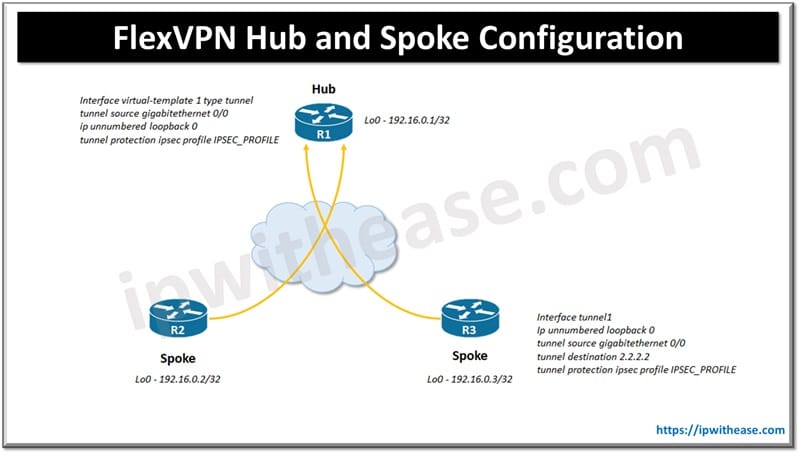
This kind of topology is useful when you want to connect multiple remote sites with a central site. In this design topology spoke routers are configured as normal static VTI having tunnel destination of hub address. Dynamic VTI is configured for hub. VTI on hub is dynamically created from pre-configured tunnel template ‘virtual template’ where tunnel is initiated by Spoke router or peer. For each spoke tunnel dynamic tunnel spawns separate ‘virtual interface’ which inherits configuration of cloned template.
I. Hub Router Configuration
Step 1 : source IP address for tunnel or loopback interface setup
interface loopback 0
ip address 192.16.0.1 255.255.255.255
Step 2: tunnel of source WAN interface and Lo0 as IP for Tunnel (tunnel template)
interface virtual-template 1 type tunnel
tunnel source gigabitethernet 0/0
ip unnumbered loopback 0
Step 3: Symmetric PSK keyring using 0.0.0.0 address to match all peers
crypto ikev2 keyring KEYRING
 peer ANY-PEER
 address 0.0.0.0
 pre-shared-key local cisco4321
 pre-shared-key remote cisco4321
 exit
Step 4: define local identity of FQDN , peer matching to domain name , mention PSK authentication , mention keyring to use and virtual template for cloning (IKEv2) profile
crypto ikev2 profile IKEV2_PROFILE
 match identity remote fqdn domain lab1.net
 identity local fqdn R1.lab1.net
 authentication remote pre-share
 authentication local pre-share
 keyring local KEYRING
 virtual-template 2
Step 5: default transform set to be used while setting IKEv2 profile
crypto ipsec profile IPSEC_PROFILE
 set ikev2-profile IKEV2_PROFILE
Step 6: on tunnel template specify IPSec profile
interface virtual-template 2  type tunnel
 tunnel protection ipsec profile IPSEC_PROFILE
Step 7: configure dynamic routing protocol and define loopback interfaces
interface loopback 2
ip address 11.1.0.1 255.255.255.0
interface loopback2
ip address 11.1.1.1 255.255.255.0
router eigrp 2
no auto-summary
network 192.16.0.1
network 11.1.0.0 0.0.255.255
Related: GETVPN vs DMVPN
II. Spoke Router Configuration
Step 1: configure dynamic routing protocol and define loopback interfaces
interface loopback0
ip address 192.16.0.2 255.255.255.0
interface loopback2
ip address 11.3.0.1 255.255.255.0
interface loopback3
ip address 11.3.1.1 255.255.255.0

router eigrp 2
no auto-summary
network 192.16.0.2
network 11.3.0.0 0.0.255.255
Step 2: Symmetric PSK keyring using 0.0.0.0 address to match all peers
crypto ikev2 keyring KEYRING
peer ANY-PEER
address 0.0.0.0
pre-shared-key local cisco4321
pre-shared-key remote cisco4321
exit
Step 3: define local identity of FQDN , peer matching to domain name, mention PSK authentication, mention keyring to use)
crypto ikev2 profile IKEV2_PROFILE
match identity remote fqdn domain lab1.net
identity local fqdn R2.lab1.net
authentication remote pre-share
authentication local pre-share
keyring local KEYRING
Step 4: default transform set to be used while setting IKEv2 profile
crypto ipsec profile IPSEC_PROFILE
set ikev2-profile IKEV2_PROFILE
Step 5 – using Lo0 as tunnel interface specify source / destination of tunnel as hub WAN IP (Specify IPsec profile)
interface tunnel1
ip unnumbered loopback 0
tunnel source gigabitethernet 0/0
tunnel destination 2.2.2.2
tunnel protection ipsec profile IPSEC_PROFILE
To Verify Configuration
Show ip interface brief to display virtual access interface created
Show crypto ikev2 sa detailed to verify IKEv2 is established
Show crypto ipsec sa to verify Ipsec tunnel is up and traffic is assigned
ABOUT THE AUTHOR

You can learn more about her on her linkedin profile – Rashmi Bhardwaj


