Objective :- Configuration of 2 Cisco Wireless controllers over WAN or Layer 3 Link.
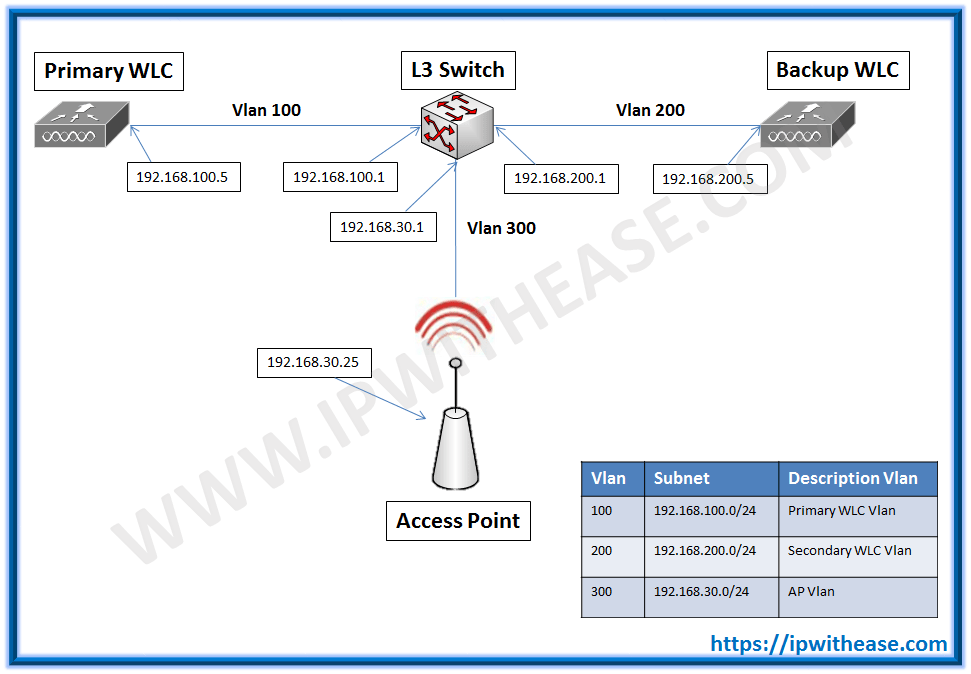
Scenario :- On the Core Switch, 3 Vlans have been created detailed as below

Configuration :- Configuration of 2 Cisco Wireless controllers to work over layer 3 or WAN Links.

WLC1 Primary:-
On the primary WLC , input the Backup controller IP (in this case 192.168.200.5) and controller name

WLC1 Primary:
Primary WLC output post configuring the parameters :-
(WLC-Primary) >show interface summary
Number of Interfaces…………………….. 6
Interface Name Port Vlan Id IP Address Type Ap Mgr Guest
——————————– —- ——– ————— ——- —— —–
management 1 100 192.168.100.5 Static Yes No
redundancy-management 1 100 192.168.100.10 Static No No
redundancy-port – untagged 169.254.100.10 Static No No
printer-vlan 1 199 10.10.199.100 Dynamic No No
service-port N/A N/A 0.0.0.0 Static No No
(WLC-Primary) >show redundancy summary
Redundancy Mode = SSO DISABLED
Local State = ACTIVE
Peer State = N/A
Unit = Primary
Unit ID = AA:BB:CC:DD:EE:FF
Redundancy State = N/A
Mobility MAC = AA:BB:CC:DD:EE:FF
Redundancy Management IP Address…………….. 192.168.100.10
Peer Redundancy Management IP Address………… 192.168.100.11
Redundancy Port IP Address………………….. 169.254.100.10
Peer Redundancy Port IP Address……………… 169.254.100.11
(WLC-Primary) >show advanced backup-controller
AP primary Backup Controller ……………….. WLC-Secondary 192.168.200.5
AP secondary Backup Controller ………………
WLC2 Secondary:
Backup WLC output post configuring the parameters :-
(WLC-Secondary) >show interface summary
Number of Interfaces…………………….. 6
Interface Name Port Vlan Id IP Address Type Ap Mgr Guest
——————————– —- ——– ————— ——- —— —–
management 1 200 192.168.200.5 Static Yes No
redundancy-management 1 200 192.168.200.10 Static No No
redundancy-port – untagged 169.254.200.10 Static No No
printer-vlan 1 199 10.10.199.100 Dynamic No No
service-port N/A N/A 0.0.0.0 Static No No
virtual N/A N/A 1.1.1.1 Static No No
(WLC-Secondary) >show redundancy summary
Redundancy Mode = SSO DISABLED
Local State = ACTIVE
Peer State = N/A
Unit = Secondary – HA SKU
Unit ID = GG:HH:II:JJ:KK:LL
Redundancy State = N/A
Mobility MAC = GG:HH:II:JJ:KK:LL
Redundancy Management IP Address…………….. 192.168.200.10
Peer Redundancy Management IP Address………… 192.168.200.11
Redundancy Port IP Address………………….. 169.254.200.10
Peer Redundancy Port IP Address……………… 169.254.200.11
(WLC-Secondary) >show advanced backup-controller
AP primary Backup Controller ……………….. 0.0.0.0
AP secondary Backup Controller ………………
L3 Switch Configuration :
L3-SWITCH1#show cdp neighbors
Device ID Local Interface Hold time Capability Platform Port ID
WLC-Secondary Gig 1/0/1 152 H AIR-CT550 Gig 0/0/1
TEST-AP-1 Gig 1/0/7 142 R T AIR-CAP12 Gig 0.1
WLC-Primary Gig 1/0/3 140 H AIR-CT550 Gig 0/0/1
L3-SWITCH1#show runn
!
interface GigabitEthernet1/0/1
Switchport access vlan 200
Switchport mode access
!
interface GigabitEthernet1/0/3
Switchport access vlan 100
Switchport mode access
end
!
interface GigabitEthernet1/0/7
switchport access vlan 300
switchport mode access
end
Testing:
========
APs configured with dhcp option 43 to join the Primary WLC (192.168.100.5).
Once the APs join the Primary WLC , under high availability configure the Primary and the Secondary WLCs with IP address.

Make sure you have configured n the primary WLC the details of Backup Primary Controller:

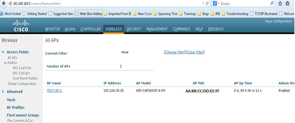
APs initially were on the Primary WLC :

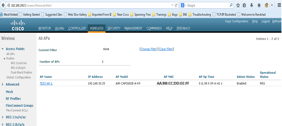
Once the connectivity to the Primary WLC is lost (We shut down the port to the Primary-WLC on the Switch). We find the APs automatically falling back to the Secondary.
AP-SWITCH1(config)#int gig 1/0/3
AP-SWITCH1(config-if)#shut
AP-SWITCH1(config-if)#
1w1d: %LINK-5-CHANGED: Interface GigabitEthernet1/0/3, changed state to administratively down
1w1d: %LINEPROTO-5-UPDOWN: Line protocol on Interface GigabitEthernet1/0/3, changed state to down

ABOUT THE AUTHOR

You can learn more about her on her linkedin profile – Rashmi Bhardwaj


