OSPF Packet Types
There are five types of OSPF packets, namely- Hello, Database description, Link-state request, Link-state update and Link-state acknowledgement. Let’s discuss all these OSPF packet types in detail:

1. THE HELLO PACKET :

The hello packets are sent over a period of time on all interfaces for the purpose of establishing and maintaining neighbour relationships. Hello packets are multicast on the networks having multicast capability, which enables discovery of neighboring routers dynamically. The inhabitance of differences among hello packets can form neighbor relationships by agreeing certain parameters.
The purpose of Hello protocol can be summarized as follows:
- Hello packets are used to discover OSPF neighbours.
- Hello packets advertise certain parameters (some of the must match in order to become the router’s neighbor).
- On Broadcast or NBMA networks Hello packets are used to elect DR/BDR roles.
- Hello packets are used as a keepalive mechanism. If the router does not hear the neighbors’ Hello packets in a given time (DeadInterval), it considers it down and invalidates information obtained from it.
- Hello packets ensure bidirectional communication. The router must see its own RouterID in the ‘neighbor’ field of the Hello packet it receives.
Related – EIGRP Stub Connected
The Hello Packet Structure and fields information is detailed below –
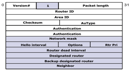
- Network Mask is the address mask of the interface from which the packet was sent. If this mask does not match the mask of the interface on which the packet is received, the packet will be dropped. This technique ensures that routers become neighbors only if they agree on the exact address of their shared network.
- Hello Interval, as discussed earlier, is the period, in seconds, between transmissions of Hello packets on the interface. If the sending and receiving routers don’t have the same value for this parameter, they do not establish a neighbor relationship.
- Options are described in “Options Field,” later in this chapter. This field is included in the Hello packet to ensure that neighbors have compatible capabilities. A router might reject a neighbor because of a capabilities mismatch.
- Router Priority is used in the election of the DR and BDR. If set to zero, the originating router is ineligible to become the DR or BDR.
- Router Dead Interval is the number of seconds the originating router will wait for a Hello from a neighbor before declaring the neighbor dead. If a Hello is received in which this number does not match the Router Dead Interval of the receiving interface, the packet is dropped. This technique ensures that neighbors agree on this parameter.
- Designated Router is the IP address of the interface of the DR on the network (not its Router ID). During the DR election process, this may only be the originating router’s idea of the DR, not the finally elected DR. If there is no DR (because one has not been elected or because the network type does not require DRs), this field is set to 0.0.0.0.
- Backup DR is the IP address of the interface of the BDR on the network. Again, during the DR election process, this may only be the originating router’s idea of the BDR. If there is no BDR, this field is set to 0.0.0.0.
- Neighbor is a recurring field that lists all RIDs of all neighbors on the network from which the originating router has received a valid Hello in the past Router Dead Interval.
Note – The fields Area ID, Hello Interval, Router Dead Interval and Authentication information (AuType & Authentication) should match on neighbors to form adjacency. For example, when the Hello interval is changed on a router, the receiving router does not accept the Hello packet due to mismatch of Hello timer.
Related- OSPF Neighbor States
2. THE DATABASE DESCRIPTION PACKET :
At the time of adjacency is being initialized, these packets are exchanged. These packets describe topological database contents. The database may be described by using multiple packets. A poll-response procedure is used for the description of multiple packets usage. Among the routers, one is designated to be master, and the other a slave. The Database Description packets are sent by the slave after sending the Database Description packets by the master.
The Database Description Packet Structure and fields information is detailed below –
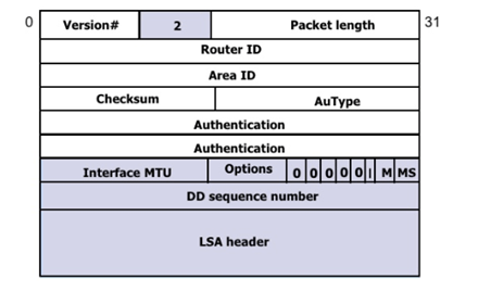
- Interface MTU is the size, in octets, of the largest IP packet that can be sent out the originator’s interface without fragmentation. This field is set to 0x0000 when the packet is sent over virtual links.
- Options are described in “Options Field,” later in this chapter. The field is included in the Database Description packet so that a router may choose not to forward certain LSAs to a neighbor that doesn’t support the necessary capabilities.
- The first five bits of the next octet are unused and are always set to 00000b.
- I-bit, or Initial bit, is set to 1 when the packet is the initial packet in series of DD packets. Subsequent DD packets have I-bit = 0.
- M-bit, or More bit, is set to 1 to indicate that the packet is not the last in a series of DD packets. The last DD packet has M-bit = 0.
- MS-bit, or Master/Slave bit, is set to 1 to indicate that the originator is the master (that is, is in control of the polling process) during a database synchronization. The slave has MS-bit = 0.
- DD Sequence Number ensures that the full sequence of DD packets is received in the database synchronization process. The sequence number is set by the master to some unique value in the first DD packet, and the sequence is incremented in subsequent packets.
- LSA Headers list some or all of the headers of the LSAs in the originator’s link-state database. See the section “Link State Header,” for a full description of the LSA header; the header contains enough information to uniquely identify the LSA and the particular instance of the LSA.
3. THE LINK STATE REQUEST PACKET:
A router may find the parts of its topological database are out of date, after database description package exchange with a neighboring router. The Link State Request packet is utilized for requesting the pieces of the neighbor’s database which are more up to date. There may be a need to utilize multiple Link State Request packets.
The Link State Request Packet Structure and fields information is detailed below –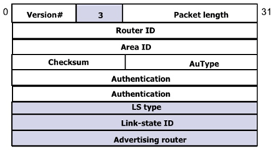
- Link State Type is the LS type number, which identifies the LSA as a Router LSA, Network LSA, and so on. Type numbers are listed in Table 8-4.
- Link State ID is a type-dependent field of the LSA header. See the section “Link State Header” and the LSA-specific sections for a full description of how the various LSAs use this field.
- Advertising Router is the Router ID of the router that originated the LSA.
4. THE LINK STATE UPDATE PACKETS:

The Link State Update Packet Structure and fields information is detailed below –
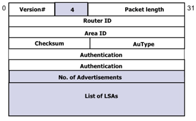
- Number of LSAs specifies the number of LSAs included in this packet.
- LSAs are the full LSAs as described in OSPF LSA formats. Each update can carry multiple LSAs, up to the maximum packet size allowed on the link.
5. THE LINK STATE ACKNOWLEDGE PACKETS:

The reliability of flooding link state advertisement is made by explicitly acknowledging flooded advertisements. The accomplishment of this acknowledgement is done through the sending and receiving of Link Sate Acknowledgement packets. A single Link State Acknowledgement packet is used to acknowledge the multiple link state advertisements.
The Link State Acknowledge Packet Structure and fields information is detailed below –
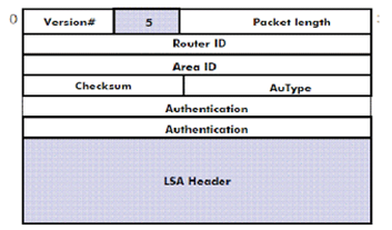
- LSA Header is List of LSA Headers being acknowledged.
Continue Reading:
OSPF Area Types: Detailed Explanation
OSPF Router Types: Detailed Explanation
ABOUT THE AUTHOR

You can learn more about her on her linkedin profile – Rashmi Bhardwaj


