For ease of understanding, below IP address subnets have been carved out to explain the concept Load Balancing across various deployment scenarios –
Client IP range = 100.0.0.1 to 100.0.0.4
Web Server Range = 192.168.0.21 to 192.168.0.24
Deployment Models of Server Load Balancer
Let’s understand the different Server load balancer deployment models one by one:
1-Arm Layer 2 mode (with SNAT)
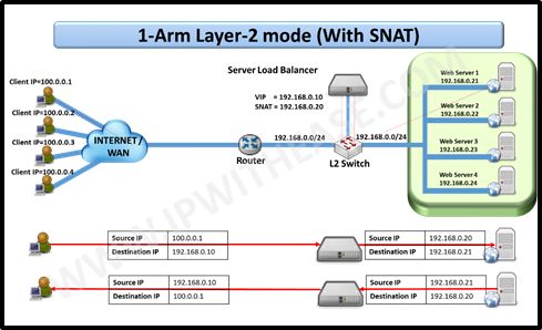
In the Layer 2 mode, SLB links to single LAN segment of 192.168.0.0/24.
In this use case, 1st client (IP 100.0.0.1) sends request to VIP 192.168.0.10 for accessing application. The SLB performs source NAT and in process initiates a request for application and changes Source from 100.0.0.1 to 192.168.0.20 and destination from 192.168.0.10 to 192.168.0.21.
Web Server 1 is chosen based on load balancing algorithm selected.
Web Server 1 responds to client (192.168.0.20 i.e. SLB will be the destination client for web server 1).On receiving the response from web Server 1, SLB rewrites the Source address to its VIP (192.168.0.21 to 192.168.0.20) and destination address to that of Client IP (192.168.0.20 to 100.0.0.1).
1-Arm Layer 3 mode (with SNAT)

In the Layer 3 mode, SLB links to 2 LAN segment of i.e. 200.0.0.0/24 (Outside) and 192.168.0.0/24 (Inside).
In this use case, 1st client (IP 100.0.0.1) sends request to VIP 200.0.0.10 for accessing application. The SLB performs source NAT and in process initiates a request for application and rewrites Source from 100.0.0.1 to 192.168.0.20 and destination from 200.0.0.10 to 192.168.0.21.
Web Server 1 is chosen based on load balancing algorithm selected.
Web Server 1 responds to client (192.168.0.20 i.e. SLB will be the destination client for web server 1.On receiving the response from web Server 1, SLB rewrites the Source address to its VIP and destination address to that of Client IP.
1-Arm Layer 3 mode (w/o SNAT)
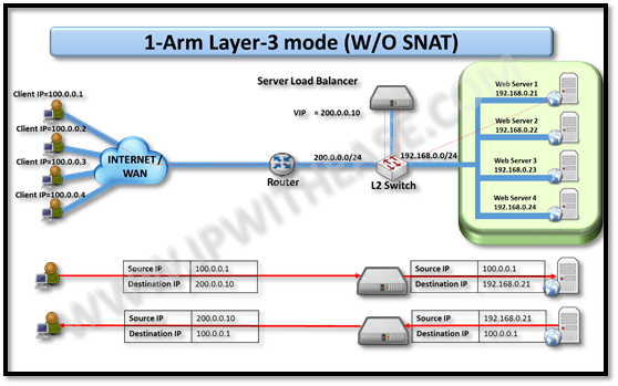
In the Layer 3 mode, SLB links to 2 LAN segment of i.e. 200.0.0.0/24 (Outside) and 192.168.0.0/24 (Inside).
In this use case, 1st client (IP 100.0.0.1) sends request to VIP 200.0.0.10 for accessing application. The SLB performs does the traffic routing however keeping the source IP of client intact and rewriting destination from 200.0.0.10 to 192.168.0.21.
Web Server 1 is chosen based on load balancing algorithm selected.
Web Server 1 responds to client (with destination IP being 100.0.0.1).On receiving the response from web Server 1, SLB routes the traffic towards client IP of 100.0.0.1 while just rewriting the source IP of web server from 192.168.0.21 to its own VIP i.e. 200.0.0.10.
Inline Layer 2 mode
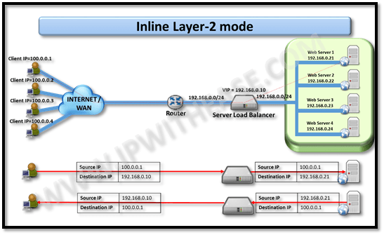
In the Inline mode, SLB sits physically installed between web (Internet) and inside links.
In layer 2 mode, both the outside and inside interface of SLB are on same LAN segment i.e. 192.168.0.0/24.In this use case, 1st client (IP 100.0.0.1) sends request to VIP 192.168.0.10 for accessing application. The SLB initiates a request for application and keeping the Source address same, rewrites destination from 192.168.0.10 to 192.168.0.21.
Web Server 1 is chosen based on load balancing algorithm selected.
Web Server 1 responds to client 100.0.0.1.On receiving the response from web Server 1, SLB rewrites the source address to that of its VIP i.e. 192.168.0.10 while no change is performed on destination IP of 100.0.0.1.
Inline Layer 3 mode
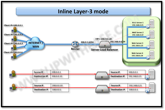
In the Inline mode, SLB sits physically installed between web (Internet) and inside links.
In layer 3 mode, outside and inside interface of SLB are on different LAN segment i.e. 200.0.0.0/24 and 192.168.0.0/24 respectively. In this use case, 1st client (IP 100.0.0.1) sends request to VIP 200.0.0.10 for accessing application. The SLB in turn initiates a request for application and keeping the Source address same, rewrites destination from 200.0.0.10 to 192.168.0.21.
Web Server 1 is chosen based on load balancing algorithm selected.
Web Server 1 responds to client 100.0.0.1.On receiving the response from web Server 1, SLB rewrites the source address to that of its VIP i.e. 200.0.0.10 while no change is performed on destination IP.
Continue Reading:
Server Load Balancer: How it works?
ABOUT THE AUTHOR

You can learn more about her on her linkedin profile – Rashmi Bhardwaj

