In scenario like working on Data Center design or for head office requiring combination of WAN Optimization, high availabilityand Security infrastructure, we sometimes come across nonstandard requirements like the one shown below, which can be achieved by tweaking of routing and switching instances –
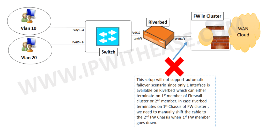
There are multiple User VLANs (Vlan 10 and 20) which need to traverse via Riverbed and then Firewall pair in cluster to reach other sites via the WAN Cloud. However, problem scenario is that Riverbed is left with only 1 interface on LAN and 1 on WAN side to support.
The 1st diagram shows what the repercussions are if we connect riverbed with single interface on each side. We need to manually move the cable from 1st Firewall Chassis to 2nd Firewall Chassis (both parts of FW Cluster) in case 1st chassis is down.
Now , the solution lies is performing some tweaking in and fooling the switch and make understand the traffic does not belong to its own but a different VLAN.
. The changes performed as shown in the below diagram –
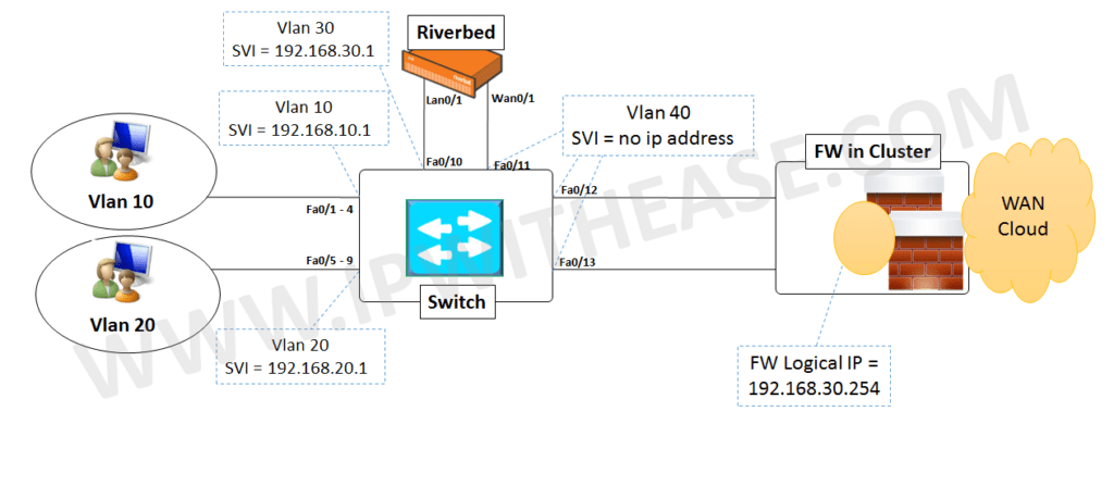
Let’s understand how the devices have been configured from below table –

Note – In this case, Riverbed WAN Optimizer is performing Layer 2 functionality for in-path mode and not achieving any Routing between Vlan 30 and Vlan 40.
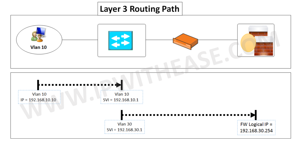
As shown in the table, when VLAN 10 and 20 user traffic reaches Switch, it will have a default route pointing towards 192.168.30.254 which is the Firewall Cluster. The Switch needs mac address of Firewall Cluster IP which is learnt on Vlan 30 connected port (Fa0/10) .The frame/packet moves out port Fa0/10 of Switch towards LAN0/1 of RB and next moves out WAN0/1 towards Switch port Fa0/11 and ultimately exiting out from Fa0/12 and Fa0/13 to reach firewall Cluster IP of 192.168.30.254.The tweaking here includes configuring ports Fa0/11 , 12 and 13 as part of Vlan 40 (In reality Vlan 30 traffic is taking Vlan 40 as Layer 2 path) and extending towards Firewall cluster. Notable is that Vlan information does not traverse on Access ports (Only trunk ports carry VLAN information).
The Layer 3 traffic path is shown as below for clarity.
ABOUT THE AUTHOR

You can learn more about her on her linkedin profile – Rashmi Bhardwaj

