Table of Contents:
Cloud based data centers provide application resiliency and network allocation flexibility due to their geographically dispersed locations placement. However, to meet the requirement the network must provide layer 2, layer 3 and storage connectivity between these dispersed data centers. The connectivity must be established without compromising the autonomy of data centers and stability of the overall network. This is required for effective deployment of distributed data centers which support flexibility in workload mobility and application availability.
Today we look more in detail about Cisco Overlay transport virtualization solution, its architecture and components, and the benefits of OTV.
Overlay Transport Virtualization (OTV)
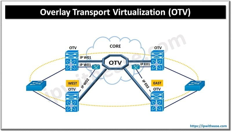
Overlay Transport Virtualization (OTV) provides extension of layer 2 connectivity across diverse transport. OTV is a ‘mac address in IP’ technique which supports layer 2 VPNs for extension of LAN over any means of transport. The transport could be Layer 2 , layer 3 , IP switched, or anything else as long as it can carry IP packets using MAC routing principle. OTV provides an overlay to enable layer 2 connectivity between layer 2 domains; keeping domains independent and preserve their fault-isolation, load balancing and resiliency benefits of IP based interconnection.
Related: What is the difference between VxLAN and OTV?

OTV encapsulates packets inside an IP header and sets the Do not fragment (DF) bit for OTV control and data packets traversing the transport network. The encapsulation attaches 42 bytes to original IP maximum transition unit (MTU) size. It is a recommended practice to use the max possible MTU size packet supported by transport while configuring the joining interface and all layer 3 interfaces.
Components & Terminology
Let’s look at some components and terminologies associated with OTV more in detail for better understanding.
- Edge Device – The OTV edge device is required to perform OTV functions. Multiple OTV edge devices can be there in a site. OTV requires a transport service license. If an OTV device is created in non-default VDC then you will need an advanced service license.
- Internal Interfaces – are site facing interfaces of edge devices; which carry VLAN extension through OTV. OTV configuration is not required on these as they are standard layer 2 interfaces.
- Join Interfaces – uplink to edge device; layer 3 point to point routed interface, required to join physically overlay network
- Overlay Interface – is virtual interface where OTV configuration is done. This is a logical multi-access multicast enabled interface, layer 2 packet encapsulation happens in IP unicast and multicast here.
- Authoritative Edge Device (AED) – is responsible for advertisement of MAC addresses over its VLANs; forward VLAN traffic inside /outside the site.
- Site VLAN – used to discover OTV neighbour edge in local site
- Site Identifier – common unique site ID must be used by same site edge devices
- MTU – join interfaces and core interfaces neighbouring require MTU of > 1542
- FHRP Isolation – used to provide same active default gateway to each data center site
- SVI Separation – SVI separation is enforced currently for VLANs extended across OTV link
Benefits of Overlay Transport virtualization (OTV)
- Scalable – extends layer 2 LANs over any network which supports IP. Can scale across multiple data centers seamlessly
- Simple – transparent deployment over existing network without the need for redesign. Minimal configuration commands are needed
- Resilient – Existing layer 3 boundaries are preserved. Having built in loop prevention. Provides Site independence and failure boundary preservation between data centers
- Efficient – available bandwidth is optimized using equal cost multipathing and optimal multicast replication. Provides multi-point connectivity and fast failover.
Some additional benefits of using OTV are:
- Use of any network transports which supports IP
- Provisioning Layer 2 and 3 connectivity with same dark fiber connections
- Unknown unicasts are not sent to overlay hence supports native unknown unicast flood isolation
- No explicit configuration of Bridge Data Protocol Unit (BDPU) filtering as it supports native spanning tree protocol isolation
ABOUT THE AUTHOR

You can learn more about her on her linkedin profile – Rashmi Bhardwaj


