Introduction to DMVPN
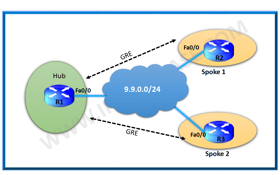
In DMVPN phase 1 we saw that there is no direct Spoke – Spoke communication. In phase 2 there will be a multipoint GRE tunnel interface on the spokes as well instead of point-point GRE tunnel. So we have direct spoke-spoke tunneling in phase 2. When a spoke router wants to reach to another spoke router it will send out a NHRP resolution request to HUB to find the NBMA address of the other spoke.
Let us use the same topology diagram as the one we used in our post for DMVPN phase 1 configuration as below:

DMVPN Phase 2
Most of the configuration on the hubs and the Spoke will remain the same as in phase 1 except:
- Now the Spokes will have Multipoint GRE tunnel interface.
- There will be no manual destination configured on the spokes.
The first packet from spoke to spoke will traverse the hub after which we will see a dynamic tunnel created towards the spoke and the packet there onwards will reach directly the Spoke.
Configuration
R1:
ip address 1.1.1.1 255.255.255.255
!
interface Tunnel0
ip address 192.168.10.1 255.255.255.0
no ip redirects
no ip next-hop-self eigrp 100 #So that hub doesn’t list itself as the next hops for the routing updates of the spoke.
no ip split-horizon eigrp 100
ip nhrp authentication cisco
ip nhrp map multicast dynamic
ip nhrp network-id 10
tunnel source FastEthernet0/0
tunnel mode gre multipoint
!
interface FastEthernet0/0
ip address 9.9.0.1 255.255.255.0
!
router eigrp 100
network 1.1.1.1 0.0.0.0
network 192.168.10.0
R2:
ip address 2.2.2.2 255.255.255.255
!
interface Tunnel0
ip address 192.168.10.2 255.255.255.0
ip nhrp authentication cisco
ip nhrp map 192.168.10.1 9.9.0.1
ip nhrp map multicast 9.9.0.1
ip nhrp network-id 1
ip nhrp nhs 192.168.10.1
tunnel source FastEthernet0/0
tunnel mode gre multipoint
!
interface FastEthernet0/0
ip address 9.9.0.2 255.255.255.0
!
router eigrp 100
network 2.2.2.2 0.0.0.0
network 192.168.10.0
R3:
ip address 3.3.3.3 255.255.255.255
!
interface Tunnel0
ip address 192.168.10.3 255.255.255.0
ip nhrp authentication cisco
ip nhrp map 192.168.10.1 9.9.0.1
ip nhrp map multicast 9.9.0.1
ip nhrp network-id 1
ip nhrp nhs 192.168.10.1
tunnel source FastEthernet0/0
tunnel mode gre multipoint
!
interface FastEthernet0/0
ip address 9.9.0.3 255.255.255.0
!
router eigrp 100
network 3.3.3.3 0.0.0.0
network 192.168.10.0
Verification
On spokes we see only a single tunnel created towards the Hub.
R3#sh dmvpn
N – NATed, L – Local, X – No Socket
# Ent –> Number of NHRP entries with same NBMA peer
NHS Status: E –> Expecting Replies, R –> Responding, W –> Waiting
UpDn Time –> Up or Down Time for a Tunnel
==========================================================================
Interface: Tunnel0, IPv4 NHRP Details
Type:Spoke, NHRP Peers:1,
# Ent Peer NBMA Addr Peer Tunnel Add State UpDn Tm Attrb
—– ————— ————— —– ——– —–
1 9.9.0.1 192.168.10.1 UP 00:00:45 S
R2#sh dmvpn
N – NATed, L – Local, X – No Socket
# Ent –> Number of NHRP entries with same NBMA peer
NHS Status: E –> Expecting Replies, R –> Responding, W –> Waiting
UpDn Time –> Up or Down Time for a Tunnel
==========================================================================
Interface: Tunnel0, IPv4 NHRP Details
Type:Spoke, NHRP Peers:1,
# Ent Peer NBMA Addr Peer Tunnel Add State UpDn Tm Attrb
—– ————— ————— —– ——– —–
1 9.9.0.1 192.168.10.1 UP 00:00:45 S
The routing table on R2 shows the route for R3 is learnt directly via the R3 and vice versa.
R2#sh ip route | i 3.3.3.3
R3#sh ip route | i 2.2.2.2
We see the initial trace goes via the Hub and post that we will also see a Dynamic Spoke-Spoke Tunnel created:
R2#traceroute 3.3.3.3 source 2.2.2.2
Tracing the route to 3.3.3.3
VRF info: (vrf in name/id, vrf out name/id)
1 192.168.10.1 96 msec 24 msec 24 msec
2 *
192.168.10.3 92 msec 28 msec
Next we see a Dynamic tunnel gets created between Spoke 1 and Spoke 2.
R2#sh dmvpn
N – NATed, L – Local, X – No Socket
# Ent –> Number of NHRP entries with same NBMA peer
NHS Status: E –> Expecting Replies, R –> Responding, W –> Waiting
UpDn Time –> Up or Down Time for a Tunnel
==========================================================================
Interface: Tunnel0, IPv4 NHRP Details
Type:Spoke, NHRP Peers:2,
# Ent Peer NBMA Addr Peer Tunnel Add State UpDn Tm Attrb
—– ————— ————— —– ——– —–
1 9.9.0.1 192.168.10.1 UP 00:05:08 S
1 9.9.0.3 192.168.10.3 UP 00:01:06 D
R3#sh dmvpn
N – NATed, L – Local, X – No Socket
# Ent –> Number of NHRP entries with same NBMA peer
NHS Status: E –> Expecting Replies, R –> Responding, W –> Waiting
UpDn Time –> Up or Down Time for a Tunnel
==========================================================================
Interface: Tunnel0, IPv4 NHRP Details
Type:Spoke, NHRP Peers:2,
# Ent Peer NBMA Addr Peer Tunnel Add State UpDn Tm Attrb
—– ————— ————— —– ——– —–
1 9.9.0.1 192.168.10.1 UP 00:05:36 S
1 9.9.0.2 192.168.10.2 UP 00:01:35 D
R2#sh ip nhrp
Tunnel0 created 00:07:20, never expire
Type: static, Flags: used
NBMA address: 9.9.0.1
192.168.10.3/32 via 192.168.10.3
Tunnel0 created 00:03:10, expire 01:56:51
Type: dynamic, Flags: router used
NBMA address: 9.9.0.3
We now further see that the trace towards R3 from R2 goes directly without traversing the Hub:
R2#traceroute 3.3.3.3 source 2.2.2.2
Tracing the route to 3.3.3.3
VRF info: (vrf in name/id, vrf out name/id)
1 192.168.10.3 40 msec 20 msec 32 msec
Continue Reading:
DMVPN Phase 1 Configuration scenario
How to configure GRE Tunnel in CISCO Router
ABOUT THE AUTHOR

You can learn more about her on her linkedin profile – Rashmi Bhardwaj


