Introduction to GRE Tunnel
Generic Routing Encapsulation (GRE) is a tunnelling protocol which is used to transport IP packets over a network .Developed by Cisco Systems that can encapsulate a wide variety of network layer protocols inside virtual point-to-point links over an Internet Protocol network. Later it become industry standard (RFC 1701, RFC 2784, RFC 2890).
GRE (Generic Routing Encapsulation) allows Routing of IP packets between private IPv4 networks which are separated over public IPv4 internet. GRE (Generic Routing Encapsulation) also supports encapsulating IPv4 broadcast and multicast traffic.
GRE Tunnel Configuration
To configure the tunnel source and destination, issue the “tunnel source {ip-address | interface-type}” and “tunnel destination {host-name | ip-address}” commands under the interface configuration mode for the tunnel.
Example Scenario
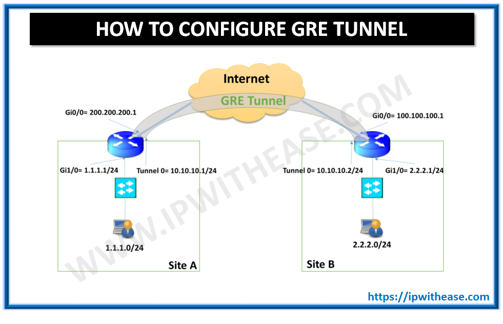
A sample scenario is created below to make audience more clear on configuring GRE Tunnel across sites.

Shown above are 2 Sites Site A and Site B. Site A has LAN subnet 1.1.1.0/24 and WAN (Internet) IP 200.200.200.1 while Site B has LAN subnet as 2.2.2.0/24 and WAN (Internet) IP 100.100.100.1.We need to configure a GRE tunnel across both the sites for LAN to LAN communication to happen.
Step 01: Use following commands to create a tunnel interface, configure an IPv4 Address for the new tunnel interface and to configure a source and destination for the tunnel interface in R1. R1#configure terminal Step 02: Use following commands to create a tunnel interface, configure an IPv4 Address for the new tunnel interface and to configure a source and destination for the tunnel interface in R2.R2#configure terminal Step 03: Use the following commands to configure OSPF for inter-site routing in R1. Step 04: Use the following commands to configure OSPF for inter-site routing in R2. Now that configuration is done on Both Router R1 and R2 of sites A and B respectively , GRE tunnel is configured and both side LAN users can communicate to each other. GRE encapsulation structure is shown below – You can learn more about her on her linkedin profile – Rashmi Bhardwaj
R1(config)#interface tunnel 0
R1(config-if)#ip address 10.10.10.1 255.255.255.252
R1(config-if)#ip mtu 1400
R1(config-if)#ip tcp adjust-mss 1360
R1(config-if)#tunnel source 200.200.200.1
R1(config-if)#tunnel destination 100.100.100.1
R1(config-if)#exit
R1(config)#exit
Enter configuration commands, one per line. End with CNTL/Z.
R2(config)#interface tunnel 0
R2(config-if)#ip address 10.10.10.2 255.255.255.252
R2(config-if)#ip mtu 1400
R2(config-if)#ip tcp adjust-mss 1360
R2(config-if)#tunnel source 100.100.100.1
R2(config-if)#tunnel destination 200.200.200.1
R2(config-if)#exit
R2(config)#exit
R1#configure terminal
R1(config)#router ospf 1
R1(config-router)#network 1.1.1.1 0.0.0.0 area 0
R1(config-router)#network 10.10.10.1 0.0.0.0 area 0
R1(config-router)#exit
R1(config)#exit
R2#configure terminal
R2(config)#router ospf 1
R2(config-router)#network 2.2.2.1 0.0 0.0 area 0
R2(config-router)#network 10.10.10.2 0.0.0.0 area 0
R2(config-router)#exit
R2(config)#exitGRE Encapsulation Structure

ABOUT THE AUTHOR


