Table of Contents:
GLBP Protocol
GLBP is the abbreviation for “Gateway Load Balancing Protocol”. GLBP is a virtual gateway protocol similar to HSRP and VRRP. However, unlike others, GLBP has capability of using multiple physical gateways simultaneously. In case of HSRP or VRRP, only one physical gateway in a standby/redundancy group is responsible for packet forwarding, others remain inactive in standby/backup state. GLBP has a little different mechanism of traffic forwarding.
It elects one AVG (Active Virtual Gateway) for each group. Other group members act as backup of AVG. This is monitored using hello and holdtime timers, which are 3 and 10 seconds by default. The elected AVG then assigns a virtual MAC address to each member of the global load balancing protocol group, thus enabling AVFs (Active Virtual Forwarders). Each AVF assumes responsibility for forwarding packets sent to its virtual MAC address.
By default, GLBP routers use the local multicast address 224.0.0.102 to send hello packets to their peers every 3 seconds over UDP 3222 (source and destination).
Related – HSRP vs VRRP vs GLBP
Load Balancing Methods
There are multiple methods for load balancing:
- Round-robin: the AVG will hand out the virtual MAC address of AVF1, then AVF2, AVF3 and gets back to AVF1 etc.
- Host-dependent: A host will be able to use the same virtual MAC address of an AVF as long as it is reachable.
- Weighted: If you want some AVFs to forward more traffic than others you can assign them a different weight.
Key Points of GLBP Protocol
Below key points can summarizes GLBP protocol:
- GLBP allows all the Gateways to forward the traffic simultaneously and additionally act as backup for each toher.
- AVG redundancy is controlled by GLBP priority and AVF redundancy is implemented using AVF weight value and two additional timers.
- By default, GLBP routers use the local multicast address 224.0.0.102 to send hello packets to their peers every 3 seconds over UDP 3222 (source and destination).
- Cisco implemented IPv6 support for GLBP in IOS release 12.2(33).
- This is monitored using hello and holdtime timers, which are 3 and 10 seconds by default
- GLBP uses load balancing mechanisms like – Round robin, Hosts dependent and weighted.
- GLBP routers use the local multicast address 224.0.0.102 to send hello packets operates on UDP port 3222
Example scenario: GLBP Protocol
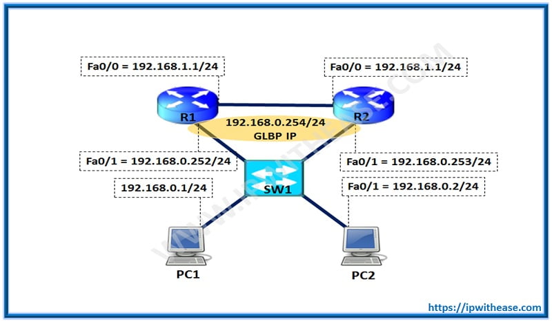
Below scenario is helpful in understanding the concept of GLBP and its supporting terms :

Routers R1 and R2 LAN Interfaces run GLBP (Group 1) as per below Configuration:
R1(config)#interface FastEthernet0/1
R1(config-if)#ip address 192.168.0.252 255.255.255.0
R1(config-if)#glbp 1 ip 192.168.0.254R1(config)#interface FastEthernet0/0
R1(config-if)#ip address 192.168.12.1 255.255.255.0
R2(config)interface FastEthernet0/1
R2(config-if)ip address 192.168.0.253 255.255.255.0
R2(config-if)glbp 1 ip 192.168.0.254R2(config)interface FastEthernet0/0
R2(config-if)ip address 192.168.12.2 255.255.255.0
The following is the output from “show glbp brief” which displays primary and backup AVG Router including details on Active Virtual forwarders:
Interface Grp Fwd Pri State Address Active router Standby router
Fa0/1 1 – 100 Active 192.168.0.254 local 192.168.0.253
Fa0/1 1 1 – Active 0007.b400.0101 local –
Fa0/1 1 2 – Listen 0007.b400.0102 192.168.0.253 –
Interface Grp Fwd Pri State Address Active router Standby router
Fa0/1 1 – 100 Standby 192.168.0.254 192.168.0.252 local
Fa0/1 1 1 – Listen 0007.b400.0101 192.168.0.252 –
Fa0/1 1 2 – Active 0007.b400.0102 local –
As per above output, R1 becomes the AVG for group 1
If required, below commands can also be issued to show more detail on GLBP AVG and AVF details including AVG priority and AVF weights.
Now that devices are configured and we are now ready to test the path taken by PC1 and PC2. (Note PC-1 and PC-2 are Routers configured as End hosts for testing purpose.)
Tracing the route to 192.168.12.11 192.168.0.253 36 msec 72 msec 68 msec
2 192.168.12.1 124 msec 88 msec 92 msec
PC-1 takes the path via R2 , which is the AVF for traffic from 192.168.0.1 towards 192.168.12.1.
Tracing the route to 192.168.12.11 192.168.0.252 92 msec 72 msec 60 msec
As shown above, PC-2 takes the path via R1 , which is the AVF for traffic from 192.168.0.2 towards 192.168.12.1.
Hence, the above output shows that both the gateways ie R1 and R2 and are active and simultaneously forward the traffic based on the decision taken by AVG active Router.
GLBP Commands
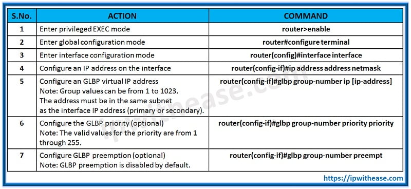
Below table shows commonly used GLBP commands to configure basic GLBP and to alter GLBP’s behavior:

Continue Reading:
Multiple HSRP (MHSRP): Load Sharing FHRP
Load Sharing vs Load Balancing
ABOUT THE AUTHOR

You can learn more about her on her linkedin profile – Rashmi Bhardwaj


