This article shares some of helpful network design scenario for a branch site that I came through while working for a customer project.
SCENARIO –
A new branch site was coming up which would connect to Data Center over MPLS/WAN Link.
The key requirements are included as below –
- 1 Link on Router for WAN termination. The Link will be on Ethernet Copper medium (supporting 10/100/1000 Mbps speed).
- WAN Bandwidth supported upto 30 Mbps
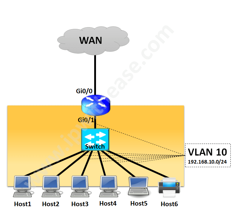
- 5 ports for Laptops and 1 port for Printer/FAX machine. All on Copper Ethernet and supporting upto 1 Gbps speed
- Laptops will be assigned IP from Local DHCP Server (Router as DHCP Server) from 192.168.10.0/24 subnet and 1 IP fixed for Printer/FAX machine.
- Space is a constraint and proposed design should consider minimal space and power supply/input.
SOLUTION –
Considering the above requirement, it seems one would go ahead with requirement of having –
- Router supporting WAN Bandwidth above 30 Mbps like cisco 1941 Series Router
- By Default 1941 comes with 2 Copper (10/100/1000 Mbps) interfaces
- Layer 2 Switch like Cisco 2960x platform.
- Router will be configured as DHCP Server for endpoints

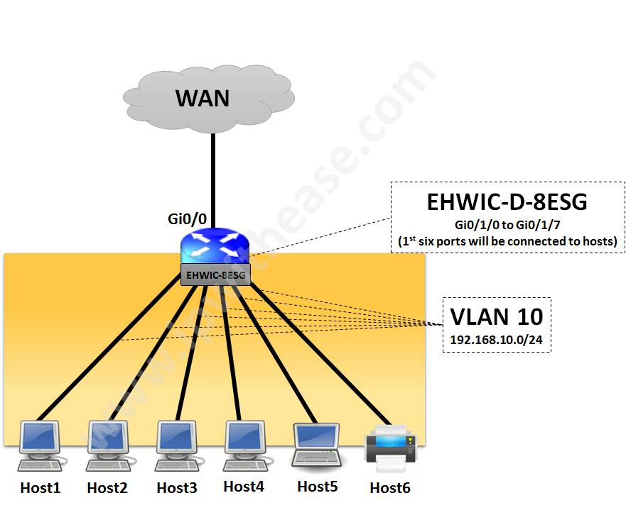
However, an essential requirement was optimal utilization of space. Therefore a better solution meeting the above requirements would be to have an EtherSwitch module (EHWIC-D-8ESG) on the Router which will serve following functions –
- Provide 8 Ethernet ports (10/100/1000 Mbps) for end point termination
- Will be installed within Cisco 1941 Router with no additional space required for Layer 2 Switch.
Now we need to perform following activity on 1941 Router loaded with EHWIC-D-8ESG card.
Step 1 – Configure WAN Interface and IP Routing
Step 2 – Configure LAN interface of Router
Step 3 – Configure DHCP Pool on Router as per table

Step 1 – Configure WAN Interface and IP Routing
R1(config-if)#no sh
R1(config-if)#ip addr 192.168.12.2 255.255.255.252
R1(config-if)#description connection to ISP
R1(config-if)#exit[/alert-announce]
Now, default route will be configured towards the provider Router ie PE as below
Step 2 – Configure LAN interface of Router
1st Vlan 10 in Vlan database and SVI IP will be configured
R1(vlan)#vlan 10
VLAN 10 added:
Name: VLAN0010
R1(vlan)#exitR1(config)#interface Vlan10
R1(config-if)#ip address 192.168.10.1 255.255.255.0[/alert-announce]
Next , Interfaces Gi0/1/0 to Gi0/1/7 will be configured as switchport members (access ports) of Vlan 10
R1(config-if)#switchport
R1(config-if)#switchport mode access
R1(config-if)#switchport access vlan 10
R1(config-if)#no shut[/alert-announce]
Step 3 – Configure DHCP Pool on Router
1st configure addresses to be excluded from DHCP Pool ie Internet Router (R1 with IP = 192.168.10.1) and Printer (IP = 192.168.10.2)
R1(config)#ip dhcp excluded-address 192.168.10.2[/alert-announce]
Next,configure the DHCP Pool with Gateway Router address and DNS entries
R1(dhcp-config)#network 192.168.2.0 255.255.255.0
R1(dhcp-config)#default-router 192.168.2.2
R1(dhcp-config)#dns-server 4.2.2.2[/alert-announce]
From the above pool, Printer can be connected on port Gi0/1/5 and asigned IP 192.168.10.2. All the end points (except printer) can be assigned IP address from DHCP with default gateway being Internet Router (LAN IP 192.168.10.1).
The above design is valid for Cisco ISR G2 Series (1900,2900 and 3900 Series) as well as Cisco ISR G3 Series (4000 Series) Routers.In ISR G2 , Etherswitch module part code is “EHWIC-XXX” while 4000 Series etherswitch module part code is “NIM-ES2-XXX“.
ABOUT THE AUTHOR

You can learn more about her on her linkedin profile – Rashmi Bhardwaj


