To ensure that world over data communication systems must be compatible to communicate with each other, a standard has been created by ISO called Open System Interconnection (OSI) model.
7 Layers of OSI Model
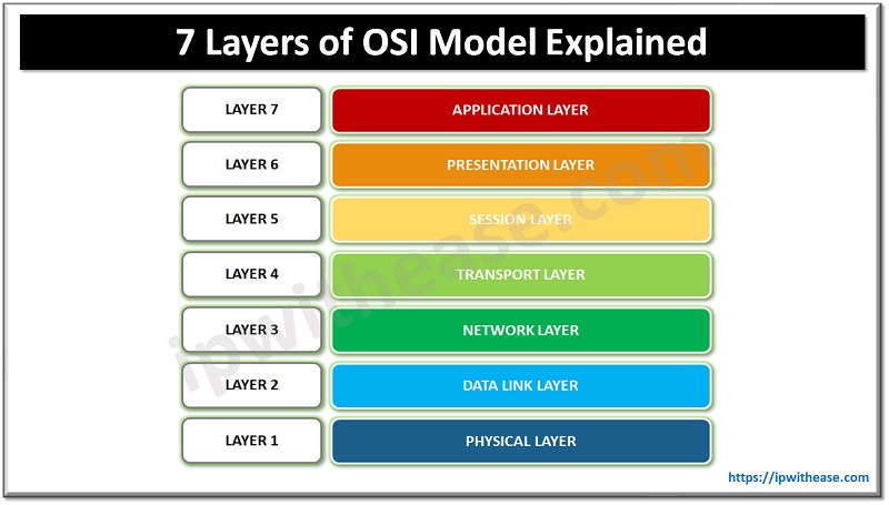
The Open Systems Interconnect (OSI) model has seven layers. The highest layer being “Application Layer” while the ‘lowest’ in the hierarchy being Physical layer. The layers in hierarchy is as below –
- Application
- Presentation
- Session
- Transport
- Network
- Data Link
- Physical

LAYER 7: APPLICATION LAYER
- It is the topmost layer of OSI model and provides the interface between the network protocol and the software.
- This layer mainly holds application programs.
Some of key application protocols which work on this layer are below –
- File Transfer Protocol (FTP)
- Simple Mail Transfer Protocol (SMTP) and Post Office Protocol (POP)
- Internet Message Access Protocol (IMAP)
- Hypertext Transfer Protocol (HTTP)
- Simple Network Management Protocol (SNMP)
- Network News Transfer Protocol (NNTP)
LAYER 6 – PRESENTATION LAYER
The functions performed at the Presentation layer of the OSI are:
- Protocol / Data conversion
- Code translation.
- Data encryption and decryption
- Data compression
- Character set conversion
- Interpretation of commands.
Some of examples of functions formed at presentation layer include ASCII to EBCDIC translation, password encryption etc.
LAYER 5 – SESSION LAYER
Session layer is responsible for gracefully closing sessions and for session check and recovery. It is used in applications that make use of remote procedure calls. The Session layer utilizes Transport layer to establish communication sessions.
The major attributes and functions of session layer include –
- Session layer is the 5th layer of OSI model.
- To manage and synchronize the conversation between two applications.
- Source to destination session layer streams of data are resynchronized suitably to avoid data loss and allow messages not to end prematurely.
LAYER 4 – TRANSPORT LAYER
The Transport layer is responsible for handling transport functions such as reliable or unreliable delivery of the data from source to destination. The transport layer is responsible to break the data segments into smaller packets. The transport layer will be responsible for opening all of the packets , fragmentation and reassembly of messages.
The key functions of Transport layer for network communication are enlisted below –
- Guaranteed data delivery
- Name resolution
- Flow control
- Error detection
- Error recovery
The common Transport protocols at this layer are –
- Transmission Control Protocol (TCP) is a connection-orientation protocol that offers high reliability of transporting data .Unlike UDP, in case of TCP, the application sending the data receives acknowledgement that the data was actually received.
- User Datagram Protocol (UDP) is a connectionless protocol that does not provide reliable data transport. No acknowledgements are received by the application working on UDP.
LAYER 3 – NETWORK LAYER
The Network Layer is primarily responsible for establishing the paths used for transfer of data packets between devices on the network. One of the main functions performed at the Network layer is routing. Routing enables packets to be moved among computers which are more than one link from one another.
The functions performed at the Network layer of the OSI model are listed below –
- Traffic routing to the end destination
- Routing functions; route discovery and route selection
- Frame fragmentation: A router can fragment a frame for transmission and re-assembly at the destination station.
- Packet sequence control
- End-to-end error detection, from the data sender to the receiver of data.
- Congestion control
- Network layer flow control and Network layer error control
- Accounting functions to keep track of frames forwarded by Network layer device
LAYER 2 – DATA LINK LAYER
The Data Link Layer is primarily responsible for communications between adjacent network nodes. Network switches and hubs operate at this layer which may also correct errors generated in the Physical Layer.
The responsibilities of the Data-link layer include –
- Packet Addressing
- To make sure data transfer is error free from one node to another.
- Transmitting and receiving data frames sequentially
- Media access control
- Acknowledgements and resending of frames.
- Managing the Frame traffic control. It signals the transmitting node to stop, when the frame buffers are full.
The Data-link layer receives packets from the Network layer and constructs these packets into frames to be sent over physical layer. A cyclic redundancy check (CRC) is added to the data frame to detect damaged frames. The Data-link layer can determine when a frame is lost and also requests any lost frames to be retransmitted.
The Data-link layer is divided into two sublayers –
- Logical Link Control (LLC) sublayer: The LLC sublayer provides and maintains the logical links used for communication between the devices. The functions at the LLC sublayer of the Data-link layer include the following:
- Error checking
- Frame synchronization
- Flow control
- Media Access Control (MAC) sublayer: The MAC sublayer of the Data-link layer controls the transmission of packets from one network interface card (NIC) to another over a shared media channel.
LAYER 1 – PHYSICAL LAYER
Below are the attributes of physical layer –
- It is the lowest layer of the OSI Model.
- Physical layer is the lowest layer of OSI model and transmits raw bit streams over a physical medium
- It activates, maintains and deactivates the physical connection.
- It is responsible for transmission and reception of the data over network.
- Data rates needed for transmission is defined in the physical layer by converting digital/analog bits into electrical signal or optical signals
- Devices at Physical layer handle signaling in form of bits (1s and 0s). The 1s and 0s are in represented by pulses of light or electricity
Data encoding, bit synchronization, multiplexing and link termination is also performed in this layer.
Benefits of OSI Model
- Any errors that occur in one layer can be handled separately from other layers.
- All the layers can operate automatically and independent of other above or below layers.
- OSI does not have to depend on Operating Systems or platform.
- Any hardware or software that meets the OSI standard will be able to communicate with any other hardware/software that also meets the standard
- OSI is independent of country, it doesn’t matter where the hardware/software is made
- It crosses barrier of localization of products. It has become universal standard and vendors can follow OSI standard to produce products that can be used world over.
- Different vendor products are able to interoperate since they now follow OSI as the reference model for protocols and interface standards.
- By separating the network communications into logical layers , OSI model simplifies how network protocols are designed.
- Network designs become scalable since by following layered OSI model ,modularity and layering capability increases.
- Separating communication process into layers makes software development, design, and troubleshooting easier.
Continue Reading:
What are OSI Protocols? 7 Network Layer Protocols Explained
ABOUT THE AUTHOR

You can learn more about her on her linkedin profile – Rashmi Bhardwaj


