Table of Contents:
The primary function of any switch is to receive data from connected sources and transmit it to the appropriate destination. This sets switches apart from hubs, which broadcast information to all devices in the network. It is this distinction that earns switches the label of “intelligent” devices.
The network switch plays a vital role in modern local area networks (LANs). LANs of varying sizes rely on multiple interconnected network switches. In SOHO (Small Office/Home Office) networks, a single switch is typically used, although sometimes a multi-purpose device like a residential gateway is employed to make use of small office/home broadband services like DSL and cable Internet.
In this article, we will discuss the primary functions of a layer 2 network switch.
What is a Network Switch?
An Ethernet/Network Switch functions at the data link layer (layer 2) of the OSI model. In contrast to a hub, a switch directs a message to a designated recipient.
When a host or switch on the network sends a message to another host or switch on the same network, the switch receives and interprets the frames in order to access the physical (MAC) address section of the message.
An IT Network Course will help you further enhance your practical skills related to the configuration, operation, and management of network switches.
Functions of Layer 2 Switching
- Address Learning
- Forward/Filter decisions
- Loop Avoidance
1. Address Learning
An Ethernet switch controls the transmission of frames between switch ports connected to Ethernet cables using the traffic forwarding rules described in the IEEE 802.1D bridging standard.
Related – Patch cable vs Ethernet
Traffic forwarding operates by utilizing address learning. Switches determine how to forward traffic by using the 48-bit media access control (MAC) addresses that are employed in LAN standards, such as Ethernet.
In order to achieve this, the switch acquires knowledge about the location of devices, referred to as stations in the standard, on different segments of the network by analyzing the source addresses within all the frames it receives.
When an Ethernet device transmits a frame, it includes two addresses within the frame. These addresses consist of the destination address, which indicates the device the frame is being sent to, and the source address, which represents the device that is sending the frame.
The process by which the switch “learns” is quite straightforward. Similar to other Ethernet interfaces, each port on a switch is assigned a distinct MAC address during the manufacturing process.
In contrast to a typical Ethernet device that only accepts frames specifically addressed to it, the Ethernet interface in each port of a switch operates in promiscuous mode.
In this mode, the interface is configured to capture all frames detected on the port, regardless of whether they are intended for the MAC address associated with the Ethernet interface on that specific switch port.
With the reception of each frame on a specific port, the switching software examines the source address of the frame and includes it in a table of addresses that is managed by the switch.
This is the process by which a switch’s function automatically detects which stations can be accessed through which ports.
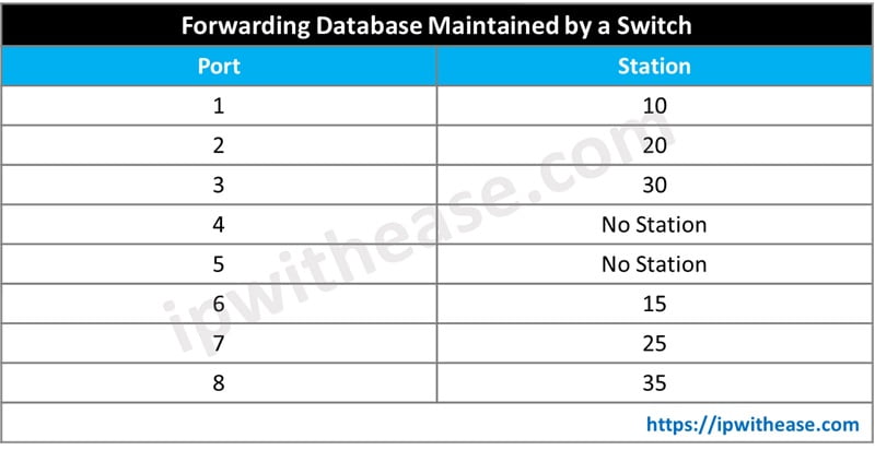
The diagram depicted below illustrates a switch connecting 6 Ethernet devices. To simplify matters, we have substituted the actual 6-byte MAC addresses with abbreviated numbers for the station addresses.
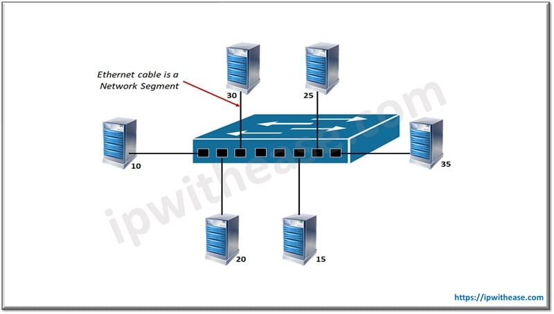
The switch collects all frames transmitted by stations and constructs a table, known as a forwarding database, which indicates the ports through which each station can be accessed.
Once every station has successfully transmitted at least one frame, the switch will have a resulting forwarding database similar to the one illustrated in the Table provided below.
Related- Functions of switch
2. Forwarding and Filtering
Forwarding refers to the action of transmitting network traffic from a device that is linked to one port of a Network Switch to another device that is connected to a different port on the switch.
When an Ethernet frame at Layer 2 reaches a port on the Network Switch, the switch performs two functions. Firstly, it reads the source MAC address of the Ethernet frame as part of the learning process. Secondly, it reads the destination MAC address as part of the forwarding process.
The port number to which the destination device is connected relies on the significance of the destination MAC address.
If the switch locates the destination MAC address in its MAC address table, it will proceed to transmit the Ethernet frame through the corresponding port associated with that MAC address.
If the destination MAC address is not present in the MAC address table, the switch will transmit the Ethernet frame to all of its ports except the port it was received from. This action is commonly referred to as flooding.
Flooding typically occurs during the initialization of a network switch. Its purpose is to prevent the loss of traffic while the switch is in the learning phase.
When the receiving device of an Ethernet frame receives and responds with a frame to the sending device, the switch examines the MAC address of the receiving device and includes it in the MAC address table as part of the learning process.
If the MAC address of the source matches the MAC address of the destination, the Ethernet frame will be discarded by the switch. This action is referred to as filtering.
This situation typically occurs when a hub is connected to a port on the switch, and both the source device and destination device are connected to the hub.
Related- Networking Scenario Based Interview Questions
3. Loop Avoidance
In practical implementations of Local Area Networking, redundant links are established to prevent total network failure in the event of a failure in one specific link.
Redundant links have the potential to create layer 2 switching loops and broadcast storms. The primary purpose of a network switch is to mitigate layer 2 switching loops and broadcast storms.
The Spanning Tree Protocol (STP) is employed to prevent network loops while still allowing for redundancy. The Spanning Tree Protocol has been developed to facilitate the transition of port states in order to address switching loops and enable the activation of the primary or preferred path.
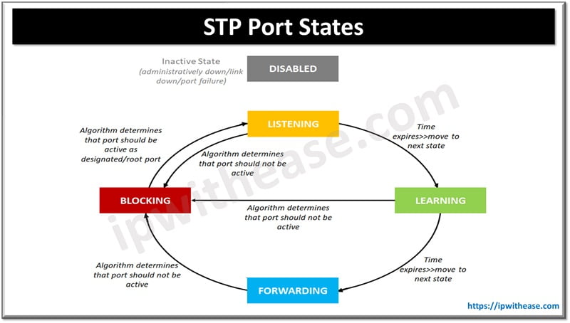
The port states of STP are as below –
- Disabled: An administrator has deliberately closed a port in this condition, or it has automatically closed because the connection was severed. It is also possible for this to be a port that has become nonfunctional due to failure. The Disabled state can be entered or exited from any other state.
- Blocking: A port that is enabled but not a root port or designated port has the potential to create a switching loop if it is active. To prevent this, the port is placed in the blocking state. During the blocking state, no station data is transmitted or received. When a port initializes (link comes up, power is turned on), it typically enters the blocking state. If it is determined through BPDUs or timeouts that the port needs to become active, it will transition from the blocking state to the listening state before reaching the forwarding state. Additionally, a blocking port may transition to the forwarding state if other links fail. Even while in the blocking state, BPDU data is still received.
- Listening: In this state, the port rejects incoming data packets but still analyzes Bridge Protocol Data Units (BPDUs) received on the port and responds accordingly if any new information is detected that would require the port to revert back to the blocked state. Depending on the information contained in the BPDUs, the port may transition to the learning state. The purpose of the listening state is to allow the spanning tree algorithm to evaluate whether the characteristics of this port, such as its cost, would make it eligible to be included in the spanning tree or if it should remain in the blocking state.
- Learning: At this state, the port is not yet actively transmitting frames. However, it does gather source addresses from received frames and includes them in the filtering database. The switch will update the MAC address table with packets detected on the port (until the timer runs out) before transitioning to the forwarding state.
- Forwarding: This refers to the operational state in which a port transmits and receives data from stations. It also keeps track of incoming BPDUs to identify if the bridge should transition the port into a blocking state to avoid a loop.
Hope you would have understood the function of the switch. Read our other blogs as well:
Difference between Network Switch and Hub
Switching Top 50 Interview Questions
ABOUT THE AUTHOR

You can learn more about her on her linkedin profile – Rashmi Bhardwaj

