In this article, we will understand SPAN, RSPAN and ERSPAN.
SPAN
SPAN feature is used in Layer 2 networks is a very good tool for troubleshooting real time traffic flows. This feature is sometimes also referred to as Port Mirroring or Port Monitoring.
Using SPAN feature traffic from a port can be duplicated to another port where a network analyzer is already connected to capture the packets for troubleshooting and analyzing the network utilization or performance.
Related- Network TAP vs SPAN
Types of SPAN:-
There are basically three types of SPAN supported on Cisco Layer 2 switches as below:
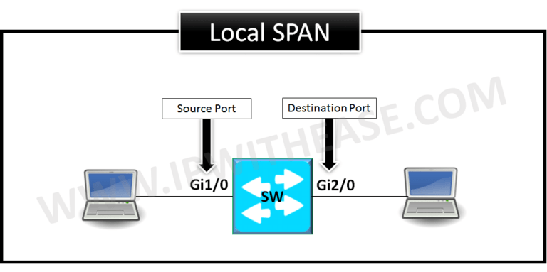
Local SPAN –
Traffic is duplicated from one port on a switch to other port on the same switch.
Remote SPAN (RSPAN) –
This works by mirroring the traffic from the source ports of an RSPAN session onto a VLAN that is dedicated for the RSPAN session. This VLAN is then trunked to other switches, allowing it’s session traffic to be transported across multiple switches. On the switch that contains the destination port for the session, traffic from the Remote SPAN session VLAN is simply mirrored out the destination port.
Encapsulated Remote SPAN (ERSPAN)
Encapsulated Remote SPAN (ERSPAN), as the name says, brings generic routing encapsulation (GRE) for all captured traffic and allows it to be extended across Layer 3 domains.
ERSPAN is a Cisco proprietary feature and is available only to Catalyst 6500, 7600, Nexus, and ASR 1000 platforms to date. The ASR 1000 supports ERSPAN source (monitoring) only on Fast Ethernet, Gigabit Ethernet, and port-channel interfaces.
Related- RSPAN vs ERSPAN
CONFIGURING LOCAL SPAN:
Local SPAN gets configured using the “monitor session” command.
Example:
SW(config)# monitor session 1 destination interface Gi2/0
SW(config)#end
Local SPAN configuration syntax on Cisco IOS release 12.2(33)SXH and beyond as shown below –
destination int fa0/24
CONFIGURING RSPAN or REMOTE-SPAN :
1st RSPAN step is to configure special VLAN which can’t be assigned to any access port.
Configuring the Special VLAN:
SW1(config-vlan)# remote-span
SW1(config-vlan)# end
SW1# show vlan remote-span
Remote SPAN VLANs
——————————————————————————
200
SW2(config-vlan)# remote-span
SW2(config-vlan)# end
SW2# show vlan remote-span
Remote SPAN VLANs
——————————————————————————
200
CONFIGURING RSPAN ON SOURCE SWITCH:
SW1(config)# monitor sessioSW1(config)# exit
Here we notice the source switch mirrors the packet from source port towards the reflector port Gi1/1.
n 1 destination remote vlan 200 reflector-port gi1/1
RSPAN Reflector Port
The reflector port forwards only the traffic from the RSPAN source session with which it is affiliated. Any device that is connected to a port that is set as a reflector port loses connectivity until the RSPAN source session is disabled.
If the bandwidth of the reflector port cannot handle the traffic from the corresponding source ports, the excess packets are dropped
The reflector port cannot be an Ether Channel port. In addition, a reflector port does not trunk and cannot do protocol filtering. A port that is used as a reflector port cannot be a SPAN source or destination port, and it cannot be a reflector port for more than one session at a time. Spanning tree is automatically disabled on a reflector port; the port remains in the forwarding state even though the port is in loopback mode.
CONFIGURING Remote SPAN ON DESTINATION SWITCH:
SW2(config)# monitor session 1 destination interface gi2/0
SW2(config)# exit
While troubleshooting IPT issues in VOIP domain if a capture isn’t possible to be taken from a IP phone then SPAN is widely used to take the capture from the switch to which the IP phone is connected and all packets from the phones are mirrored to a port where a laptop is connected with a network analyzer to capture real-time traffic.
For more information on the Source port, Destination Port and Remote SPAN VLAN characteristics please refer to link below:
https://www.cisco.com/c/en/us/support/docs/switches/catalyst-6500-series-switches/10570-41.html
ABOUT THE AUTHOR

You can learn more about her on her linkedin profile – Rashmi Bhardwaj


